In-situ mechanical property testing device and testing method

A technology of mechanical properties and testing devices, applied in measuring devices, using stable tension/pressure to test material strength, strength characteristics, etc., can solve the problem of incompatibility of stretching devices, difficulty in accurately stretching or pressing irregular samples, etc. question

Pending Publication Date: 2020-12-22
INST OF HIGH ENERGY PHYSICS CHINESE ACADEMY OF SCI +1
View PDF15 Cites 4 Cited by
  • Summary
  • Abstract
  • Description
  • Claims
  • Application Information

AI Technical Summary

Problems solved by technology

[0005] In view of the above analysis, the present invention aims to provide an in-situ mechanical performance testing device and testing method to solve the problem that the existing stretching device cannot match the synchrotron radiation experimental device, and it is difficult to achieve accurate stretching or stretching of irregular samples. pressurized problem

Method used


Image

  • In-situ mechanical property testing device and testing method
  • In-situ mechanical property testing device and testing method
  • In-situ mechanical property testing device and testing method

Examples


Embodiment 1

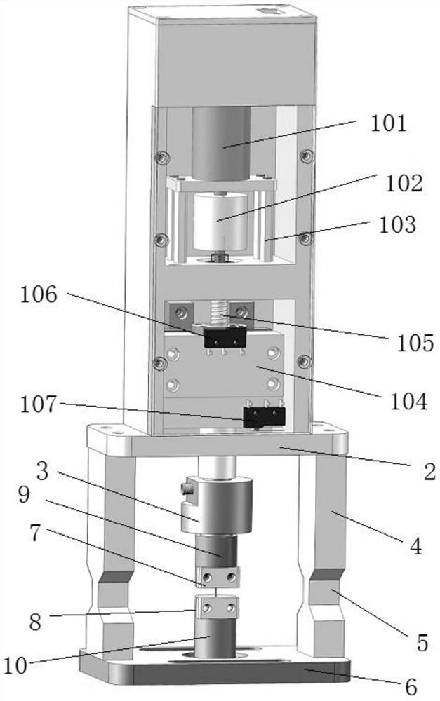
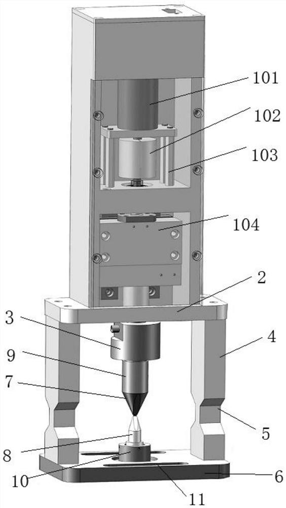
[0038] A specific embodiment of the present invention discloses a device for testing mechanical properties in situ, such as Figure 1-5 As shown, the mechanical performance testing device of the present invention includes a driving assembly 1, a support frame, a tension / compression sensor 3 and a sample holder. The driving assembly 1 is installed in the driving casing, and the driving casing is fixedly connected with the supporting frame. The support frame includes: an upper top plate 2, legs 4 and a base 6, there are two legs 4, and the upper top plate 2 and the base 6 are connected and fixed through the legs 4. The drive assembly 1 is arranged above the support frame, specifically, the drive housing of the drive assembly 1 is fixedly connected to the upper top plate 2 of the support frame.

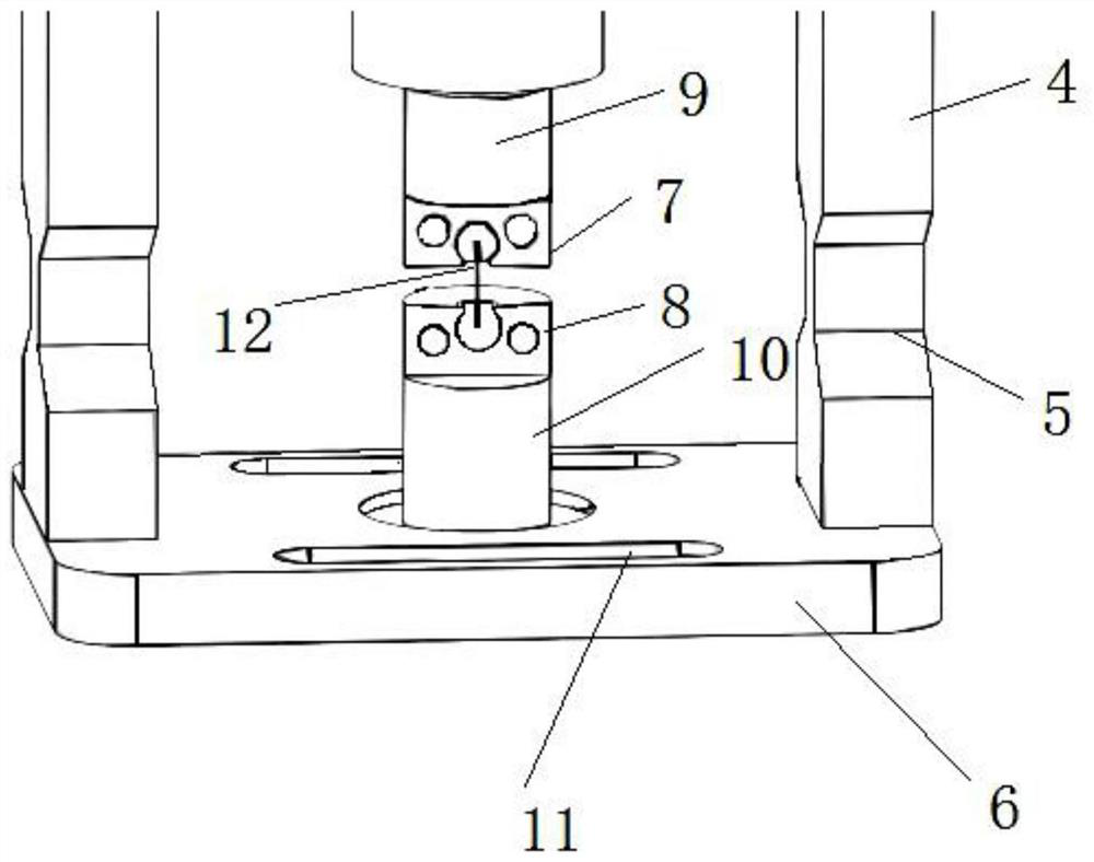
[0039] Wherein, the sample holder includes a first holder 7 and a second holder 8, the first holder 7 is located below the upper top plate 2, and the first holder 7 is driven to move up...

Embodiment 2

[0082] This embodiment provides a method for testing mechanical properties, using the in-situ mechanical testing device of Example 1 for testing, which specifically includes the following steps:

[0083] Step S1: Select a sample holder according to the type and shape of the sample 12; specifically:

[0084] When performing performance tests on non-standard shape samples, such as image 3 Sample holder shown.

[0085] When performing tensile or compression tests on standard shape samples such as films, the sample chuck of the film sample does not have an end fixing groove. Figure 5 The sample clamps shown are clamped in place.

[0086] When carrying out the pressure test on the rectangular sample, use the conical sample indenter to carry out the pressure test.

[0087] Step S2: Fix the two ends of the sample 12 to the first clamping part 7 and the second clamping part 8 respectively. specifically:

[0088] When the sample clamp is used, the sample clamp is provided with a...


PUM


Abstract

The invention relates to an in-situ mechanical property testing device and a testing method, belongs to the field of synchrotron radiation in-situ testing, and solves a problem that an irregular sample is difficult to realize tensile pressurization state simulation in the prior art. The in-situ mechanical property testing device comprises a driving assembly, a supporting frame and a sample clamping piece, wherein the sample clamping piece comprises a first clamping piece and a second clamping piece, and the first clamping piece and the second clamping piece are respectively used for fixing theupper end and the lower end of a sample; the driving assembly can drive the first clamping piece to move relative to the second clamping piece to stretch or pressurize a sample; diffraction grooves are formed in supporting legs of the supporting frame, so diffraction and imaging X-ray emergence angles not smaller than 160 degrees are achieved. According to the method, stretching or pressurizing of a standard sample and a non-characterization shape sample can be realized, and the structure and the mechanical property of the sample are detected by combining a synchrotron radiation testing system.

Description

technical field [0001] The invention relates to the technical field of mechanical performance testing equipment, in particular to a synchrotron radiation in-situ mechanical performance testing device and a testing method. Background technique [0002] With the development of experimental technologies such as synchrotron radiation CT imaging, wide-angle diffraction and small-angle scattering in the field of material structure and mechanical properties, the needs of scientific research users of the experimental station have changed from static structural characterization of samples to multi-scale dynamic characterization. [0003] Using multi-dimensional CT imaging, wide-angle diffraction and small-angle scattering and other synchrotron radiation experimental methods combined with in-situ mechanical performance testing can characterize the dynamic properties of multi-scale structures of materials in real time, and develop corresponding multi-dimensional synchrotron radiation ex...

Claims


Application Information

Patent Timeline
Patent Type & Authority Applications(China)
IPC IPC(8): G01N3/08G01N3/04G01N3/06
CPCG01N3/08G01N3/04G01N3/06G01N2203/0017G01N2203/0019G01N2203/0641
Inventor 张一董政陈兴范辉杨一鸣
Owner INST OF HIGH ENERGY PHYSICS CHINESE ACADEMY OF SCI
Why Eureka
Try Eureka