


Quick Research
Generate reliable direction feasibility study reports for your R&D in just a few steps.

Technical Q&A
Discover and master advanced knowledge NOW. Basics, ideas, possibilities, all at once.

Find Solutions
As an expert in R&D theories, this can generate solutions to your technical problems instantly.

Evaluate Feasibility
Analyze your overall solution with one click, know your potential R&D risks in advance.

Monitor Landscape
Get weekly tech updates, stay abreast of the latest tech innovations and key insights.
Image acquisition equipment correction method
The technology of an image acquisition device and a correction method, applied in the field of image processing, can solve the problems of preset parameter error, image blur, target offset, etc., and achieve the effect of improving the success rate
- Summary
- Abstract
- Description
- Claims
- Application Information
AI Technical Summary
Problems solved by technology
Method used
Image


Examples
Embodiment 1
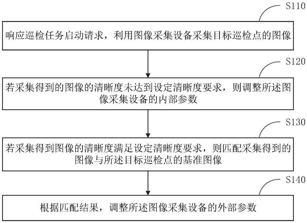
[0029] figure 1 It is a flow chart of a method for calibrating an image acquisition device provided in Embodiment 1 of the present invention. This embodiment is applicable to the situation where the image acquisition device whose mechanical structure changes is corrected to improve the quality of the acquired image. The method can be executed by a device for correcting an image acquisition device, and the device can be realized by software and / or hardware. see figure 1 , the image acquisition device correction method provided in the embodiment of the present application includes:
[0030] S110. Responding to the inspection task start request, using the image acquisition device to collect images of the target inspection point.
[0031] Among them, the inspection tasks are issued by the substation inspection system in real time, and each inspection task can correspond to an ID.
[0032] The image acquisition device refers to the device that collects the image of the target i...
Embodiment 2
[0062] figure 2 It is a flow chart of a method for calibrating an image acquisition device provided in Embodiment 2 of the present invention. This embodiment is an optional solution proposed on the basis of the foregoing embodiments. see figure 2 , the image acquisition device correction method provided in the embodiment of the present application includes:
[0063] S210. Responding to the inspection task start request, using the image acquisition device to collect images of the target inspection point.
[0064] Specifically, the responding to the inspection task start request, using the image acquisition device to collect the image of the target inspection point, includes:
[0065] Responding to the inspection task start request, acquiring the information of the target inspection point;
[0066] determining the type of the image acquisition device according to the information of the target inspection point;
[0067] Adjusting internal parameters and external parameters...
Embodiment 3
[0089] image 3 It is a flow chart of an image acquisition device calibration method provided by an embodiment of the present invention. This embodiment is an optional solution proposed on the basis of the foregoing embodiments, taking the image acquisition device as a camera as an example. see image 3 A method for correcting an image acquisition device provided in this embodiment includes:
[0090] When the inspection task is started, the current inspection point information is obtained from the database according to the inspection task ID. The current inspection point information includes the terminal type and preset position information of the current inspection point. Wherein, the current inspection point is the same as the above-mentioned target inspection point.
[0091] According to the current inspection point information, the camera type is judged, and different strategies are implemented according to different camera types. The specific content of the strategy ...
PUM
 Abstract
Description
Claims
Application Information
 - R&D Engineer
- R&D Manager
- IP Professional
- Industry Leading Data Capabilities
- Powerful AI technology
- Patent DNA Extraction
Browse by: Latest US Patents, China's latest patents, Technical Efficacy Thesaurus, Application Domain, Technology Topic, Popular Technical Reports.
© 2024 PatSnap. All rights reserved.Legal|Privacy policy|Modern Slavery Act Transparency Statement|Sitemap|About US| Contact US: help@patsnap.com