A vacuum equipment for vacuum welding or annealing of semiconductor chips

A technology of vacuum welding and vacuum equipment, which is applied in semiconductor/solid-state device manufacturing, electrical components, circuits, etc., and can solve the problems of input deviation of heavy-duty high-precision products, adding pressing devices, and pressing and tightening hinge parts. Convenient automatic loading and unloading, increase pre-compression force, easy vacuum effect

Active Publication Date: 2021-02-26
北京仝志伟业科技有限公司
View PDF5 Cites 0 Cited by
  • Summary
  • Abstract
  • Description
  • Claims
  • Application Information

AI Technical Summary

Problems solved by technology

[0006] The disadvantages of the existing vacuum equipment for vacuum welding or annealing of semiconductor chips are that the hinges will be pressed tightly by the side-hung doors and the lift-up doors, and the far-end door will be tilted, so more pressing devices are added.
For heavy-duty and high-precision products, there will be problems such as offset

Method used


Image

  • A vacuum equipment for vacuum welding or annealing of semiconductor chips
  • A vacuum equipment for vacuum welding or annealing of semiconductor chips
  • A vacuum equipment for vacuum welding or annealing of semiconductor chips

Examples


Embodiment Construction

[0040] The present invention will be described in detail below in conjunction with the implementations shown in the accompanying drawings, but it should be noted that these implementations are not limitations of the present invention, and those of ordinary skill in the art based on the functions, methods, or structures of these implementations, etc. Effective transformation or substitution all belong to the protection scope of the present invention.

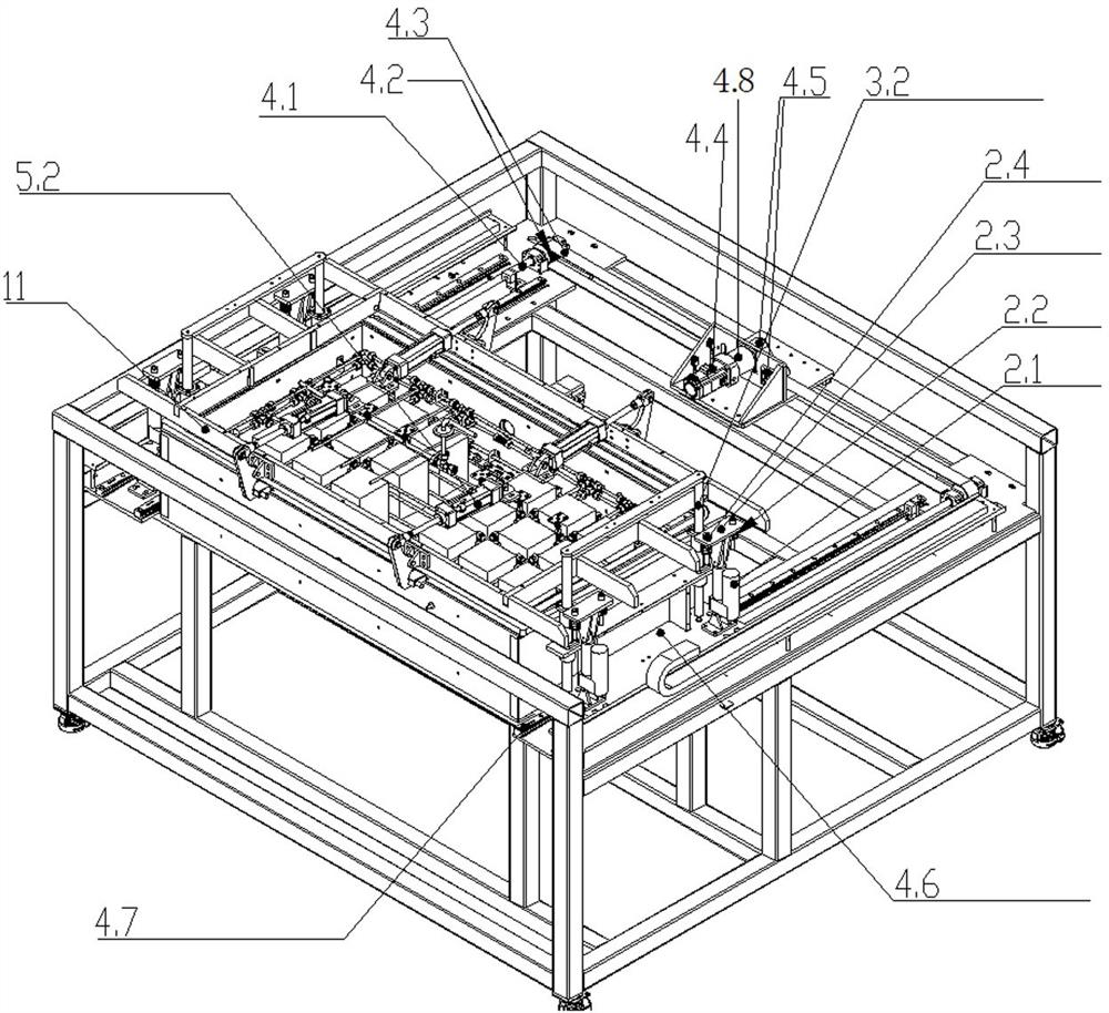
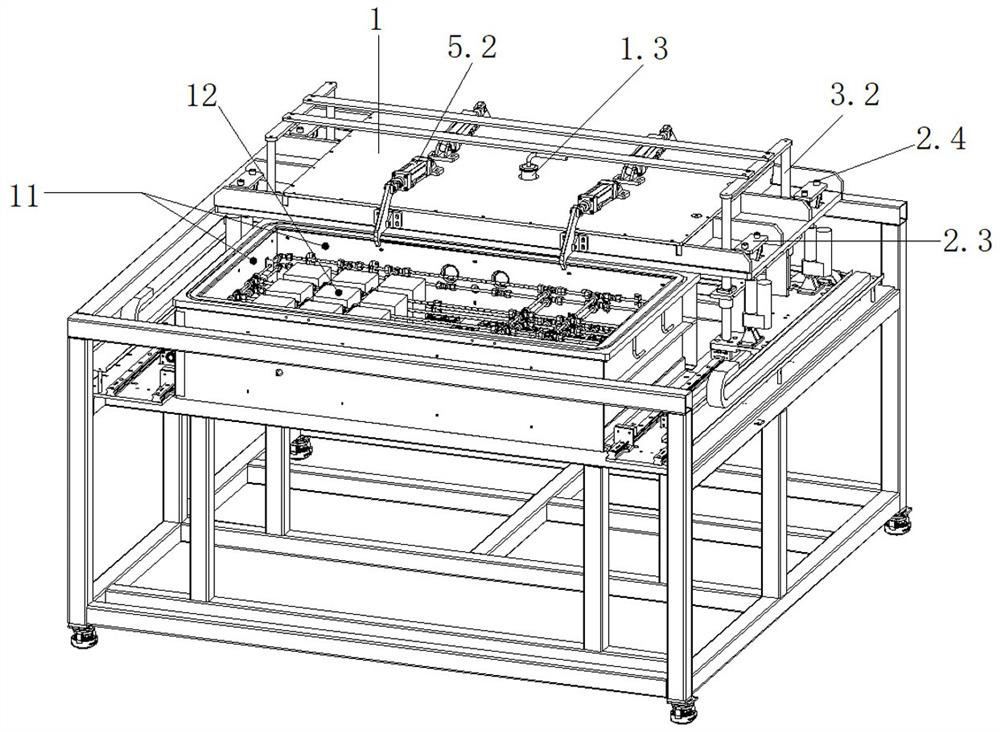
[0041] Such as figure 1 , figure 2 As shown, a vacuum equipment for vacuum welding or annealing of semiconductor chips includes a vacuum chamber 11 and a vacuum chamber upper cover 1, and also includes:

[0042] a translation mechanism, the translation mechanism is connected with the vacuum chamber upper cover 1, and can drive the vacuum chamber upper cover 1 to move horizontally relative to the vacuum chamber 11;

[0043] Lifting mechanism, the lifting mechanism is connected with the upper cover 1 of the vacuum chamber, and c...


PUM


Abstract

The invention relates to a vacuum equipment for vacuum welding or annealing of semiconductor chips, comprising a vacuum chamber and a vacuum chamber upper cover, and a translation mechanism connected with the vacuum chamber upper cover, which can drive the vacuum chamber upper cover to face The vacuum chamber moves horizontally; the lifting mechanism is connected with the upper cover of the vacuum chamber and can drive the upper cover of the vacuum chamber to move up and down relative to the vacuum chamber. The upper cover of the vacuum chamber of the present invention can be moved up and down relative to the vacuum chamber and moved horizontally. The opening and closing door does not occupy the position of the input port, which is more convenient for the robot to automatically load materials. Or the manipulator automatically loads and unloads materials, which effectively solves the problem that the horizontal input of heavy-duty products is easy to cause scratches on the jig carrier.

Description

technical field [0001] The invention relates to the technical field of high vacuum eutectic furnace, in particular to a vacuum equipment used for vacuum welding or annealing of semiconductor chips. Background technique [0002] Existing vacuum equipment for vacuum welding or annealing of semiconductor chips (for example, vacuum eutectic furnaces for processing electronic components) mostly adopts a lift-up door structure, a side-hung door structure, and a side-side vertical lift door structure, etc., as follows: [0003] Lifting door structure, the door (vacuum chamber upper cover) is set on the top of the vacuum chamber (vacuum chamber), hinged with the box body, and can be lifted up manually or automatically. [0004] Swing door structure, the door is arranged on any side around the cavity, the door is hinged with the cavity in the vertical direction, the door can be opened horizontally, most of the swing door structures are manually opened. [0005] The vertical lifting ...

Claims


Application Information

Patent Timeline
Patent Type & Authority Patents(China)
IPC IPC(8): H01L21/67
CPCH01L21/67011H01L21/67098H01L21/6719H01L21/67207
Inventor 赵永先张延忠邓燕
Owner 北京仝志伟业科技有限公司
Why Eureka
Try Eureka