


Quick Research
Generate reliable direction feasibility study reports for your R&D in just a few steps.

Technical Q&A
Discover and master advanced knowledge NOW. Basics, ideas, possibilities, all at once.

Find Solutions
As an expert in R&D theories, this can generate solutions to your technical problems instantly.

Evaluate Feasibility
Analyze your overall solution with one click, know your potential R&D risks in advance.

Monitor Landscape
Get weekly tech updates, stay abreast of the latest tech innovations and key insights.
Rolling production equipment for cable production
A production equipment and rolling technology, applied in the field of rolling production equipment for cable production, can solve the problems of inability to install the roller shaft, affect the cable production efficiency, and inability to facilitate the roller shaft, etc., to improve the accuracy of rolling processing and disassembly. And the effect of easy installation and improved efficiency
- Summary
- Abstract
- Description
- Claims
- Application Information
AI Technical Summary
Problems solved by technology
Method used
Image

Examples
Embodiment 1
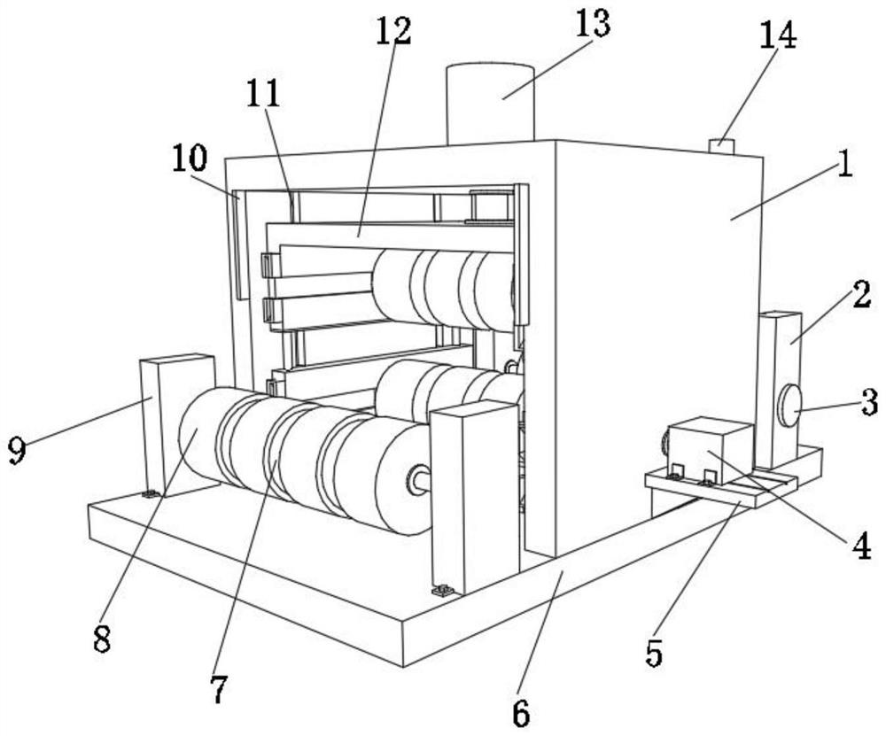
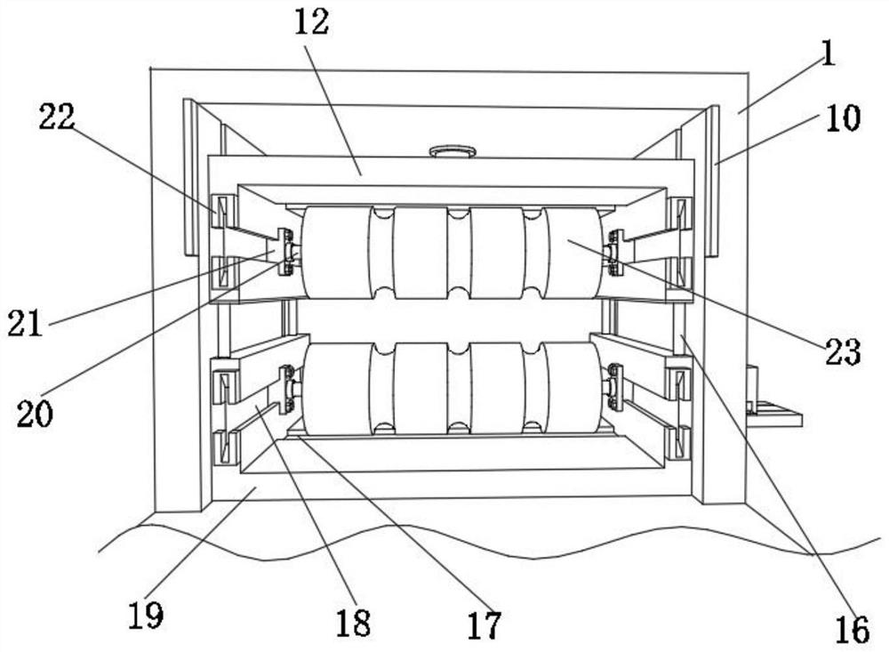
[0034] A rolling production equipment for cable production, such as Figure 1-6 As shown, it includes a protective case 1, the bottom outer wall of the protective case 1 is provided with a bottom plate 6, the top outer wall of the protective case 1 is respectively provided with an electro-hydraulic push rod 13 and a circular through hole, and the output shaft of the electro-hydraulic push rod 13 passes through a circular The through hole runs through the top outer wall of the protective shell 1, and the bottom outer wall of the output shaft of the electrohydraulic push rod 13 is provided with an upper mounting plate 12, and the inner walls on both sides of the upper mounting plate 12 are respectively provided with two mounting grooves 18, and the two mounting grooves 18 are up and down. There are four slide rails on the inner walls of both sides respectively, and two sliders 21 are slidably connected to the inner walls of the four slide rails. The slider 21 is a hollow structure....
Embodiment 2
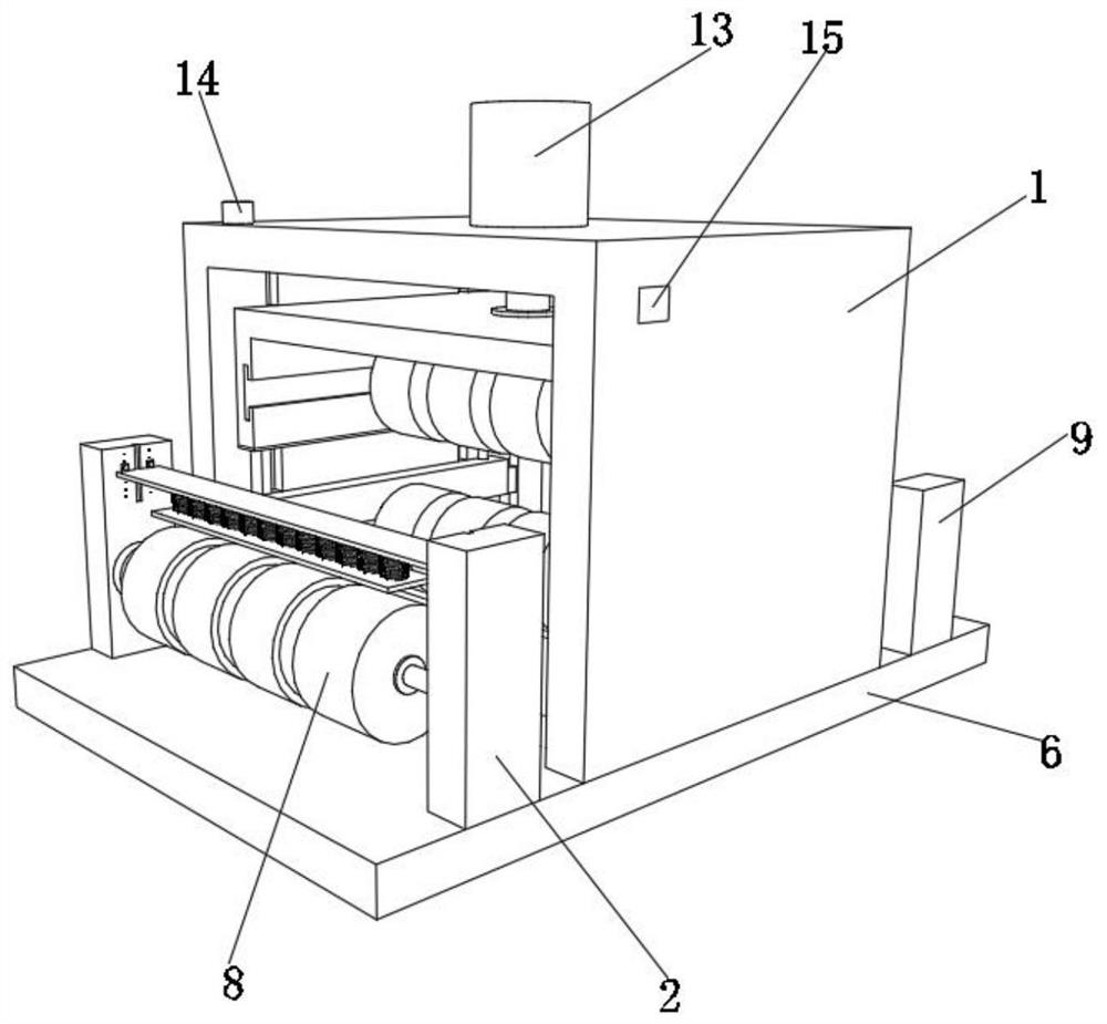
[0044] A rolling production equipment for cable production, such as Figure 5As shown, in order to allow the guide roller 8 to guide cables of different sizes; this embodiment makes the following improvements on the basis of embodiment 1: the outer walls of the two first support columns 2 are respectively provided with two slides. rail and more than three threaded holes, the inner walls of the two slide rails are slidably connected with a fixed plate 26, and the outer walls of the top of the fixed plate 26 are respectively provided with four positioning blocks 30, and the outer walls of one side of the positioning blocks 30 are fixed to the first support column 2 by screws. On one side of the outer wall, the outer wall at the bottom of the fixed plate 26 is provided with more than three telescopic columns 27 and more than three springs 28, and the outer wall at the bottom of the bottom outer wall of more than three telescopic columns 27 and more than three springs 28 is provide...
PUM
 Abstract
Description
Claims
Application Information
 - R&D Engineer
- R&D Manager
- IP Professional
- Industry Leading Data Capabilities
- Powerful AI technology
- Patent DNA Extraction
Browse by: Latest US Patents, China's latest patents, Technical Efficacy Thesaurus, Application Domain, Technology Topic, Popular Technical Reports.
© 2024 PatSnap. All rights reserved.Legal|Privacy policy|Modern Slavery Act Transparency Statement|Sitemap|About US| Contact US: help@patsnap.com