Tool for welding stud bending test
A technology of bending test and tooling, which is applied in the direction of applying stable bending force to test the strength of materials, measuring devices, instruments, etc. It can solve the problems of increasing the cost of tooling production, low detection efficiency, and limited number of times of use, etc., to save transportation costs and transportation time, simple processing steps, and rapid production
- Summary
- Abstract
- Description
- Claims
- Application Information
AI Technical Summary
Problems solved by technology
Method used
Image

Examples
Embodiment 1
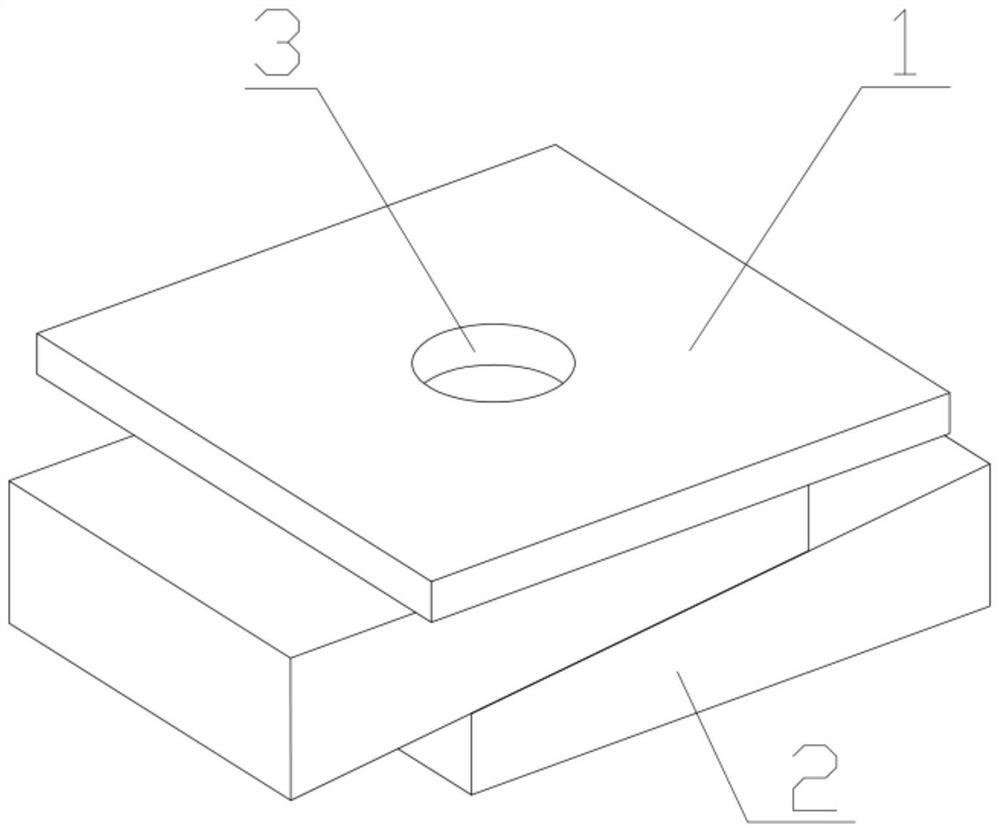
[0030] Such as figure 1 As shown, a tooling for the welding stud bending test, including a top plate 1 and a wedge-shaped spacer 2, a circular through hole 3 is opened in the middle of the top plate 1, and two wedge-shaped spacers 2 are arranged on the lower surface of the top plate 1 in the opposite direction. , two wedge-shaped pads 2 wedge-shaped surfaces coincide, the wedge-shaped surface normal of the wedge-shaped pad 2 passes through the surface of the top plate 1 and the ground on the wedge-shaped pad 2 opposite to the wedge-shaped surface is parallel to the top plate 1 surface.
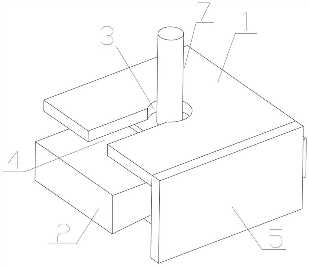
[0031] When the present invention is in use, as figure 2 As shown, a connecting piece with a certain length can be selected on site. When the length of the connecting piece is less than the length of the piece to be tested in the direction of the stud welding stud axis: first make the stud welding stud of the piece to be tested pass through the through hole of the top plate, and then Use con...
Embodiment 2
[0034] Such as image 3 As shown, the difference between this embodiment and Embodiment 1 is that the diameter of the through hole 3 on the top plate 1 is set to 35mm, and the end face of the end of the through hole axis of the top plate 1 is connected with a top plate support 5, and the through hole 3 on the top plate 1 is along the through hole. The radial direction of the hole 3 extends to the end surface of the top plate 1 to form a gap 4, the width of the gap 4 is set to 25mm, and the opening direction of the gap 4 is parallel to the intersection line between the top plate 1 and the top plate support 5.
[0035]The setting of the through hole and notch size makes the tooling suitable for stud welding studs of existing specifications, and the setting of the top plate support makes the tooling use in a wider environment, eliminating the need for repeated fixing of the top plate and connecting parts before the test, and the notch Set the matching method between the sample to...
Embodiment 3
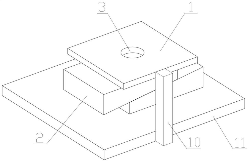
[0037] Such as Figure 4 As shown, this embodiment is an improvement on the basis of Embodiment 2. The top plate support 5 is a square plate, and the two top plate support 5 are respectively connected to the end faces on both sides of the axis of the through hole 3 on the top plate 1. The top plate 1 The extension direction of the notch 4 on the top is parallel to the plate surface of the top plate support 5, and the top plate 1 and the top plate support 5 jointly form a square through hole, and a wedge-shaped spacer 2 is placed in the square through hole, and the lower end of the top plate support 5 is fixedly connected with a Bottom plate 6., also has connecting hole near the four corners of bottom plate 6.
[0038] This embodiment is an improvement on the basis of Embodiment 2. The setting of two roof supports increases the stability of the tooling and makes the bearing capacity of the tooling stronger. At the same time, the wedge-shaped pads are also limited. To prevent t...
PUM
| Property | Measurement | Unit |
|---|---|---|
| diameter | aaaaa | aaaaa |
| width | aaaaa | aaaaa |
Abstract
Description
Claims
Application Information
 - R&D
- Intellectual Property
- Life Sciences
- Materials
- Tech Scout
- Unparalleled Data Quality
- Higher Quality Content
- 60% Fewer Hallucinations
Browse by: Latest US Patents, China's latest patents, Technical Efficacy Thesaurus, Application Domain, Technology Topic, Popular Technical Reports.
© 2025 PatSnap. All rights reserved.Legal|Privacy policy|Modern Slavery Act Transparency Statement|Sitemap|About US| Contact US: help@patsnap.com