
Embedded external prestress implementation system and reinforced RC column construction method thereof

An external prestressing and prestressing technology, applied in the direction of columns, piers, pillars, etc., can solve the problems of easy failure, anti-aging performance, poor fire resistance, and high requirements, and achieve extended service life and service life, and the overall performance of the structure. Good, reduce the effect of prestress loss

Active Publication Date: 2020-12-18
HOHAI UNIV
View PDF9 Cites 6 Cited by
  • Summary
  • Abstract
  • Description
  • Claims
  • Application Information

AI Technical Summary

Problems solved by technology

[0007] 3. After reinforcement, the fiber cloth and its anchorage end are exposed on the surface of the column without a protective layer. Its anti-aging performance and fire resistance are poor, and it is easy to fail in the natural environment, and its durability is not strong
Its structure is relatively simple, but its essence is still to apply prestress in the way of longitudinal tension. The requirements for the prestress application device are relatively high, the construction is inconvenient, and the applicability of this device is poor. Each set of reinforcement devices can only adapt to its relative size. Corresponding column, not universally applicable
In addition, when the above devices are reinforced, each reinforcement layer on the component works independently, and it is difficult to ensure that the prestress of the entire column is uniformly applied during reinforcement, which affects the integrity of the reinforcement.

Method used


Image

  • Embedded external prestress implementation system and reinforced RC column construction method thereof
  • Embedded external prestress implementation system and reinforced RC column construction method thereof
  • Embedded external prestress implementation system and reinforced RC column construction method thereof

Examples


Embodiment Construction

[0078] The present invention will be further described in detail below in conjunction with the accompanying drawings and specific preferred embodiments.

[0079] In the description of the present invention, it should be understood that the orientations or positional relationships indicated by the terms "left side", "right side", "upper", "lower" are based on the orientations or positional relationships shown in the accompanying drawings, and are only For the purpose of describing the present invention and simplifying the description, rather than indicating or implying that the device or element referred to must have a specific orientation, be constructed and operate in a specific orientation, "first", "second" and the like do not represent components importance, and therefore should not be construed as limiting the invention. The specific dimensions used in this embodiment are only for illustrating the technical solution, and do not limit the protection scope of the present in...


PUM


Abstract

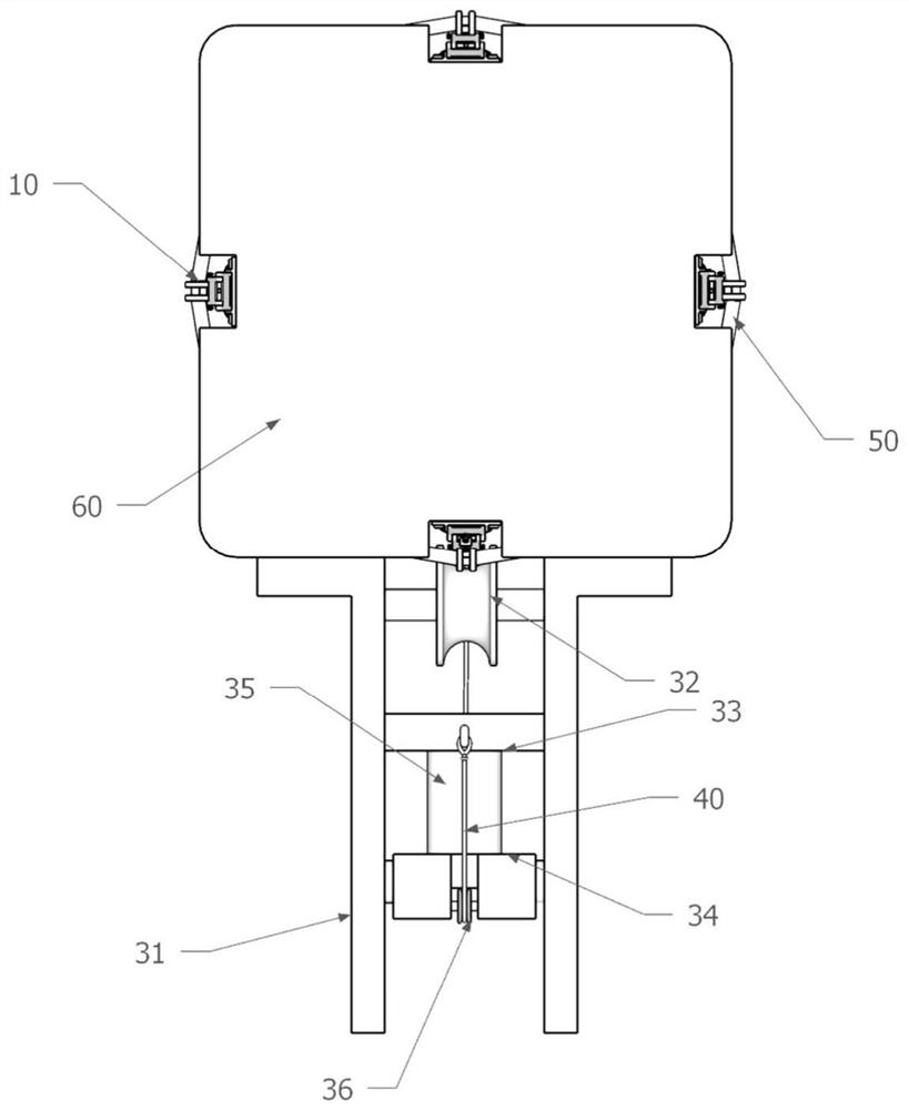
The invention discloses an embedded external prestress implementation system and a reinforced RC column construction method thereof. The embedded external prestress implementation system comprises steel strand arrangement grooves, prestress steel strands, end anchoring devices, prestress transverse tension devices, a traction line lifting device and a prestress applying device. The steel strand arrangement grooves which spirally ascend by m circles and n vertical grooves are formed in the surface of a reinforced concrete column to be reinforced. The prestress transverse tension devices are evenly distributed at the intersection points of the vertical grooves and the steel strand arrangement grooves. The traction line lifting device comprises a traction line and m traction line buckles. When the prestress applying device pulls the traction line downwards, the m traction line buckles extrude the m prestress transverse tension devices, so that m transverse tension assemblies transverselyextend, and then the prestress steel strands are transversely tensioned. By the adoption of the transverse tension mode, the expected tension effect can be achieved only by providing 1 / 5-1 / 7 of tension force during longitudinal tension. Meanwhile, anchoring is conducted firstly, then tension is conducted, end anchoring is convenient, and the anchoring difficulty is greatly lowered.

Description

technical field [0001] The invention relates to the field of reinforced concrete reinforcement, in particular to an embedded external prestress implementation system and a construction method for reinforcing RC columns. Background technique [0002] With the increase of the service life, the mechanical properties of reinforced concrete structures will continue to degrade. Under the action of natural disasters such as earthquakes, the structure will be damaged due to insufficient bearing capacity, which seriously affects the normal use of buildings. Therefore, it is necessary to take effective measures for reinforced concrete structures. The structure is reinforced. For reinforced concrete columns, the current common reinforcement methods include external steel sheet method, outsourcing FRP method, etc. The principle is mainly to increase the lateral restraint, thereby increasing the bearing capacity of the column. However, the general external reinforcement method cannot ef...

Claims


Application Information

Patent Timeline
Patent Type & Authority Applications(China)
IPC IPC(8): E04G23/02E04G21/12E04C3/34
CPCE04C3/34E04G21/121E04G23/0218E04G2021/127
Inventor 张勤杨翘楚
Owner HOHAI UNIV
Learn More