
Anti-locking charging gun, anti-locking method and device and charging pile

A charging gun and anti-lock technology, applied in charging stations, electric vehicle charging technology, electric vehicles, etc., can solve the problem of water entering the charging gun and charging connector

Active Publication Date: 2020-12-18
广州天嵌计算机科技有限公司
View PDF7 Cites 2 Cited by
  • Summary
  • Abstract
  • Description
  • Claims
  • Application Information

AI Technical Summary

Problems solved by technology

[0005] The present invention proposes an anti-locking charging gun, anti-locking method, device, and charging pile to solve the problem that the charging gun and charging connector are prone to water ingress in rainy days, and prevent rainwater from damaging the charging gun and charging circuit

Method used


Image

  • Anti-locking charging gun, anti-locking method and device and charging pile
  • Anti-locking charging gun, anti-locking method and device and charging pile
  • Anti-locking charging gun, anti-locking method and device and charging pile

Examples


Embodiment Construction

[0046] The following will clearly and completely describe the technical solutions in the embodiments of the present invention with reference to the accompanying drawings in the embodiments of the present invention. Obviously, the described embodiments are some of the embodiments of the present invention, but not all of them. Based on the embodiments of the present invention, all other embodiments obtained by persons of ordinary skill in the art without creative efforts fall within the protection scope of the present invention.

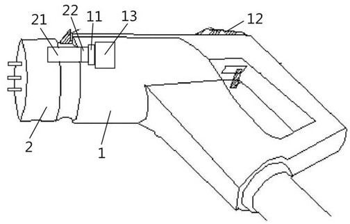
[0047] refer to figure 1 , a structural schematic diagram of an anti-lock charging gun of the present invention. The anti-lock charging gun may include: a gun body 1 and a contact kit 2 connected to each other.

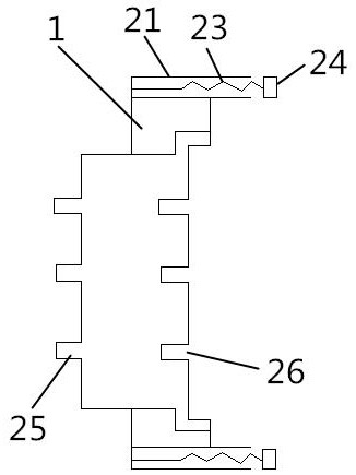
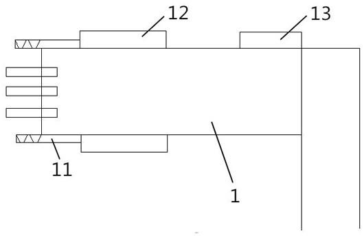
[0048] Specifically, refer to Figure 2-3 , respectively show the schematic structural diagram of the contact kit of the present invention and the structural schematic diagram of the gun body of the present invention. One side of the contac...


PUM


Abstract

The invention provides an anti-locking charging gun, an anti-locking method, an anti-locking device and a charging pile. The anti-locking charging gun comprises a gun body and a contact kit which areconnected with each other; one side of the contact kit is matched and connected with a gun head of the gun body, and the other side is connected with an automobile socket; N kit connecting holes are formed in the periphery of the contact kit; kit magnets are arranged in the kit connecting holes; N gun body connecting columns are arranged on the periphery of the gun body; the gun body connecting columns are arranged in the kit connecting holes; an electrified coil is arranged on the outer wall of each gun body connecting column, and the electrified coils are connected with the corresponding kitmagnets in a touch mode; the gun body is provided with a control circuit and two power supplies; the two power supplies include a first power supply and a second power supply; the control circuit isconnected with a charging pile server, the control circuit is connected with the first power supply and the second power supply through a double-pole-double-throw switch; and the electrified coils areconnected with the first power supply and the second power supply respectively; and the first power supply and the second power supply provide two different current flowing directions for the electrified coils respectively.

Description

technical field [0001] The invention relates to the field of charging piles, in particular to an anti-locking charging gun, an anti-locking method, a device and a charging pile. Background technique [0002] As the global automobile industry is facing the huge challenge of energy and environmental issues, it is the trend of automobile development to develop new energy electric vehicles, realize the electrification of automobile energy and power systems, and promote the strategic transformation of the traditional automobile industry. As the energy supply equipment of electric vehicles, charging piles develop rapidly along with the development of electric vehicles. [0003] Common charging piles include AC charging piles and DC charging piles. Among them, the AC charging piles charge the car's on-board charger through alternating current, and then the on-board charger charges the car battery. Therefore, the charging time will be relatively long, generally 6-8 hours. During t...

Claims


Application Information

Patent Timeline
Patent Type & Authority Applications(China)
IPC IPC(8): B60L53/16
CPCB60L53/16Y02T10/70Y02T10/7072Y02T90/14Y02T90/167Y04S30/12
Inventor 方杰俊
Owner 广州天嵌计算机科技有限公司
Learn More