
High-precision part synchronous inner and outer hole flanging machining die and method

A kind of inside-out, high-precision technology, which is applied in the field of high-precision parts processing, can solve the problems of prone to breakage, inability to carry out high-precision zero simultaneous inside and outside hole machining, low hole turning machining accuracy, etc., to ensure stability and easy hole turning. , the effect of not easy to break

Pending Publication Date: 2020-12-18
宋明义
View PDF0 Cites 0 Cited by
  • Summary
  • Abstract
  • Description
  • Claims
  • Application Information

AI Technical Summary

Problems solved by technology

[0002] When the high-precision parts are turned through the mold, the inner and outer holes of the two ends of the high-precision parts cannot be processed at the same time, and the general high-precision parts are in the process of turning holes, and the precision of ordinary mold turning holes is not high. , so that the part is prone to breakage when turning the hole, and the processed part after turning the hole cannot be automatically taken out and replaced, which will reduce the efficiency of turning the hole for high-precision parts

Method used


Image

  • High-precision part synchronous inner and outer hole flanging machining die and method
  • High-precision part synchronous inner and outer hole flanging machining die and method
  • High-precision part synchronous inner and outer hole flanging machining die and method

Examples


Embodiment Construction

[0027] The following will clearly and completely describe the technical solutions in the embodiments of the present invention with reference to the accompanying drawings in the embodiments of the present invention. Obviously, the described embodiments are only some, not all, embodiments of the present invention. Based on the embodiments of the present invention, all other embodiments obtained by persons of ordinary skill in the art without making creative efforts belong to the protection scope of the present invention.

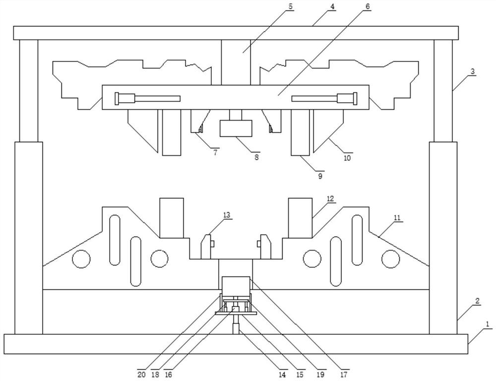
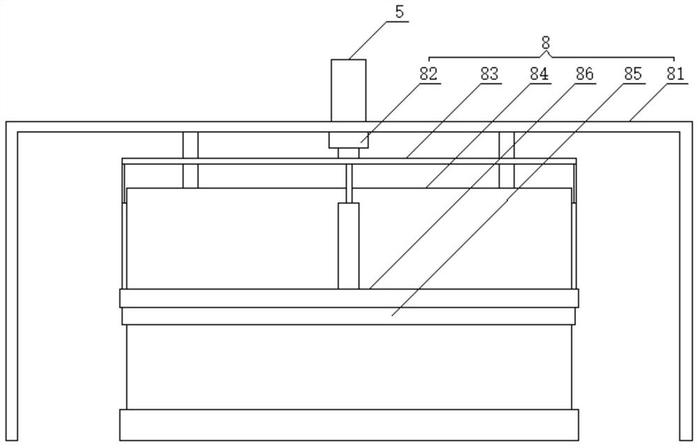
[0028] see Figure 1-5 , the present invention provides a technical solution: a high-precision parts synchronous internal and external turning hole processing mold, including a fixed bottom plate 1, guide sleeves 2 are arranged on the left and right sides of the top of the fixed bottom plate 1, and the top of the guide sleeve 2 is movably plugged with guide posts 3. The top of the guide post 3 is provided with a fixed top plate 4, and the fixed top plate 4 is ...


PUM


Abstract

The invention belongs to the technical field of high-precision part machining, and discloses a high-precision part synchronous inner and outer hole flanging machining die which comprises a fixed bottom plate. Guide sleeves are arranged on the left side and the right side of the top of the fixed bottom plate correspondingly, guide columns are movably inserted into the tops of the guide sleeves, anda fixed top plate is arranged at the tops of the guide columns. The top of the fixed top plate is connected with an electric push rod, the bottom of the electric push rod is connected with a movabledie holder, fastening devices are arranged on the left side and the right side of the bottom of the movable die holder correspondingly, the bottom of the movable end of the electric push rod is connected with an out hole flanging device, and the left side and the right side of the bottom of the movable die holder are each provided with a limiting rod and a positioning clamping plate. A fixed die holder is arranged on the inner walls of the lower ends of the guide sleeves. It is effectively guaranteed that the hole flanging position of a machined part is not prone to breakage, hole flanging canbe more easily performed on the machined part, meanwhile, inner hole flanging machining and outer hole flanging machining are conducted synchronously, coaxiality is effectively guaranteed, the machined part is good in stability and high in precision during hole flanging, the machined part obtained after hole flanging is automatically ejected out, and the machining efficiency is improved.

Description

technical field [0001] The invention relates to the technical field of high-precision parts processing, in particular to a mold and method for synchronously turning holes inside and outside of high-precision parts. Background technique [0002] When the high-precision parts are turned through the mold, the inner and outer holes of the two ends of the high-precision parts cannot be processed at the same time, and the hole-turning process of the general high-precision parts is not high. , so that the part is prone to breakage when turning the hole. At the same time, the processed parts after turning the hole cannot be automatically taken out and replaced, which will reduce the efficiency of turning the hole of high-precision parts. To this end, we propose a mold and method for synchronously turning holes inside and outside of high-precision parts. Contents of the invention [0003] The object of the present invention is to provide a mold and method for synchronously turning...

Claims


Application Information

Patent Timeline
Patent Type & Authority Applications(China)
IPC IPC(8): B21D19/08B21D37/12B21D37/16B21D43/00B21D45/04
CPCB21D19/088B21D37/12B21D37/16B21D43/003B21D45/04
Inventor 宋明义
Owner 宋明义
Learn More