Car roof solar charging equipment

A technology for charging equipment and solar panels, applied in solar thermal power generation, solar thermal energy, solar collectors, etc., can solve the problems of large cross-sectional area of ​​solar panels, blocking the driver's sight, affecting the normal driving of cars, etc. Effect of effective contact area, improvement of power generation efficiency, and increase of effective contact area

Active Publication Date: 2020-12-15
泰山启帆山东创业投资管理有限公司
View PDF8 Cites 0 Cited by
  • Summary
  • Abstract
  • Description
  • Claims
  • Application Information

AI Technical Summary

Problems solved by technology

[0004] In the above solution, the expanded solar panel has a large cross-sectional area, which will block the driver's sight and affect the normal driving of the car.

Method used


Image

  • Car roof solar charging equipment
  • Car roof solar charging equipment
  • Car roof solar charging equipment

Examples


Embodiment Construction

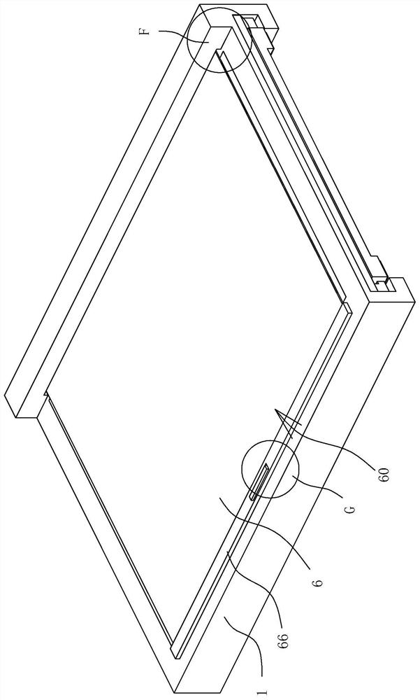
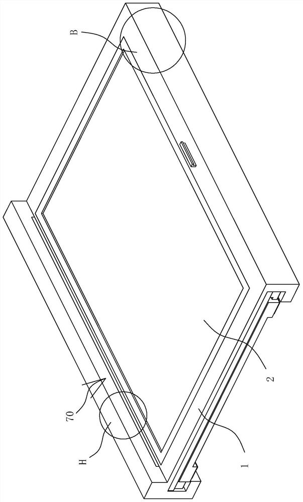
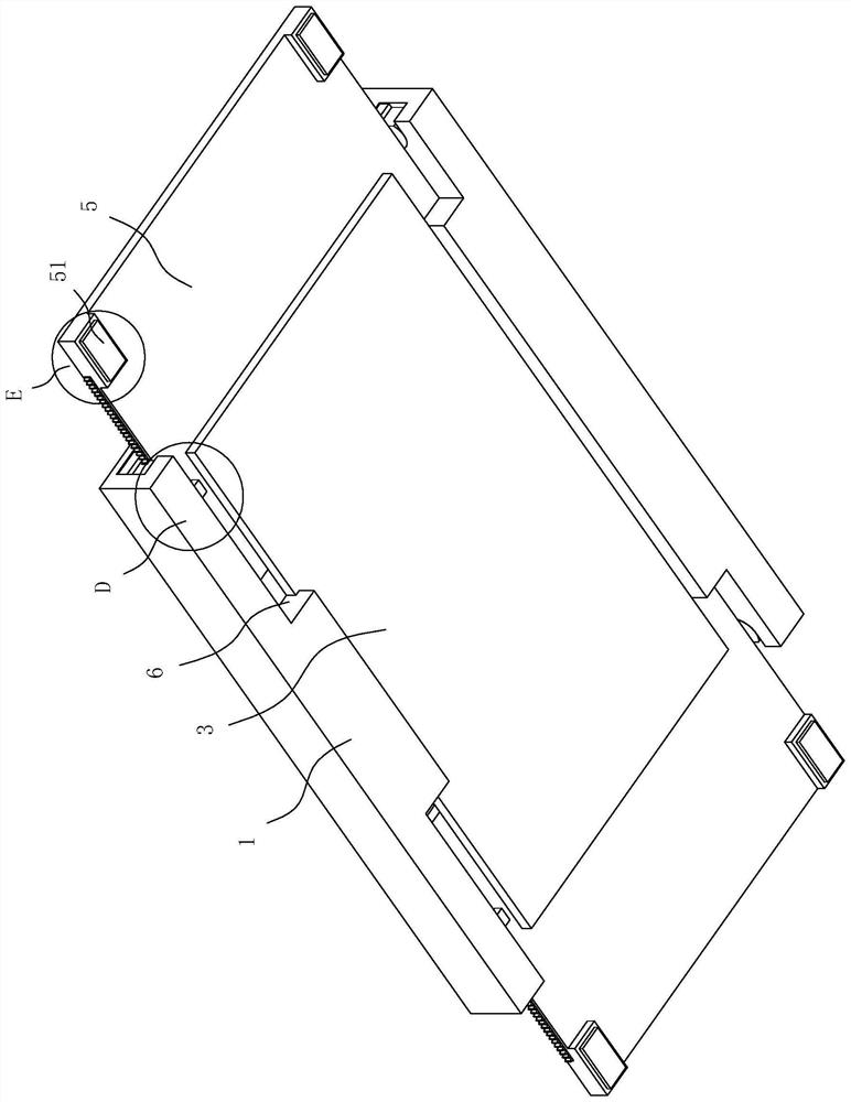
[0034] Such as Figure 1 to Figure 12 As shown, the present invention is described in detail. For the convenience of description, the orientations mentioned below are now stipulated as follows: figure 1 The up-down, left-right, front-back direction of the projection relationship itself is consistent. A kind of roof solar charging device of the present invention includes a frame 1. 3 The upper end is provided with a chute 4, and the two ends of the chute 4 are respectively provided with a second solar panel 5, the second solar panel 5 and the chute 4 are slidingly connected, between the frame 1 and the second solar panel 5 A moving mechanism 10 is provided, straight grooves 6 are respectively provided on both sides of the front end of the bottom plate 3, support mechanisms 30 are respectively provided at both ends of the chute 4, the second solar cell panel 5 is arranged in the support mechanism 30, and the second solar cell panel 5 is Both sides of the end are respectively pr...


PUM


Abstract

The invention discloses car roof solar charging equipment. The equipment comprises a rack, wherein a first solar cell panel is arranged at the upper end of the rack, a bottom plate is arranged at thebottom end of the rack, a sliding groove is formed in the upper end of the bottom plate, second solar cell panels are arranged at the two ends in the sliding groove respectively, a moving mechanism isarranged between the rack and the second solar cell panels, and straight grooves are formed in the two sides of the front end of the bottom plate respectively; two ends of the sliding groove are eachprovided with a supporting mechanism, the second solar cell panel is arranged in the supporting mechanisms, the two sides of the outer end of the second solar cell panel are each provided with a buffer mechanism, a protection mechanism is arranged at the top end of the rack; the second solar cell panel in the semi-unfolded state does not influence the normal driving of the automobile.

Description

technical field [0001] The invention belongs to the field of new energy vehicles, and relates to charging equipment, in particular to a roof solar charging equipment. Background technique [0002] The disadvantage of the prior art is that conventional solar panels installed on the limited space on the roof have insufficient power generation. For this reason, people have carried out long-term exploration, put forward various solutions. [0003] For example, the Chinese patent document discloses a sun-tracking roof folding solar panel [Application No.: 202010159213.4], which includes a caravan roof with a lifting cavity in the upper end surface, and a lifting cavity capable of moving up and down is installed in the lifting cavity. Base, the bottom wall of the lifting chamber is provided with a driving chamber, and the driving chamber is provided with a lifting device capable of driving the lifting base to move up and down; the present invention is provided with a foldable s...

Claims


Application Information

Patent Timeline
Patent Type & Authority Applications(China)
IPC IPC(8): H02S20/30H02S20/00H02S40/00B60L8/00F24S30/20
CPCB60L8/003F24S30/20H02S20/00H02S40/00H02S20/30Y02E10/47Y02E10/50Y02T10/7072
Inventor 王丽芳
Owner 泰山启帆山东创业投资管理有限公司
Why Eureka
Try Eureka