
A Method for Identifying Fault Sections and Fault Branches of Collecting Lines in Wind Farms

A technology for collecting lines and fault sections is applied in the field of identification of fault sections and fault branches of power collecting lines in wind farms. Effect

Active Publication Date: 2021-10-12
KUNMING UNIV OF SCI & TECH
View PDF11 Cites 0 Cited by
  • Summary
  • Abstract
  • Description
  • Claims
  • Application Information

AI Technical Summary

Problems solved by technology

[0004] The technical problem to be solved in the present invention is to reasonably add measuring points for the key nodes of the collector line for the complexity of the collector line structure and the singleness of configuration protection, and to propose a method for identifying the fault section and fault branch of the collector line of the wind farm , to solve the above problems

Method used


Image

  • A Method for Identifying Fault Sections and Fault Branches of Collecting Lines in Wind Farms
  • A Method for Identifying Fault Sections and Fault Branches of Collecting Lines in Wind Farms
  • A Method for Identifying Fault Sections and Fault Branches of Collecting Lines in Wind Farms

Examples


Embodiment 1

[0059] Embodiment 1: as figure 1 As shown in , the simulation model of a typical wind farm power collection system is constructed, and the specific parameters of the model are as follows:

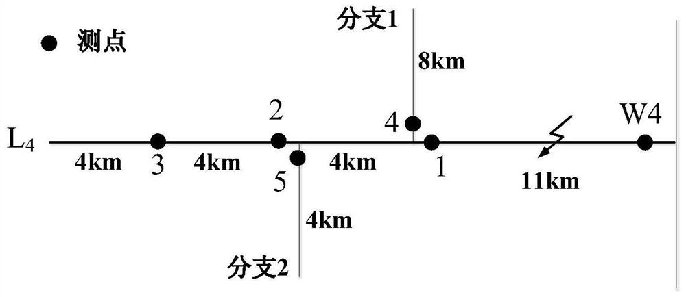
[0060] (1) There are 4 collector lines L on the 35kV collector bus 1 ~ L 4 , where L 1 ~ L 3 Each line has 3 double-fed wind turbines, L 4 Containing branches, there are a total of 8 double-fed wind turbines; a total of 17 double-fed wind turbines are connected. The doubly-fed wind turbine is connected to the collector line via a 0.69kV / 38.5kV Y / △-type box-type transformer booster. The capacity of each wind turbine is 2MW, and the total capacity of wind turbines is 17*2MW=34MW.

[0061] (2) L 1 ~ L 4 The total length of the trunk line is: 24km, 17km, 14km, 23km, of which L 1 ~ L 4 Upstream are cable lines with lengths of 20km, 13km, 10km, and 11km respectively. Downstream wind turbines are overhead lines, and the distance between every two wind turbines is 2km. L 4 The lengths o...

Embodiment 2

[0067] Embodiment 2: as figure 1 As shown in , the simulation model of a typical wind farm power collection system is constructed, and the specific parameters of the model are as follows:

[0068] (1) There are 4 collector lines L on the 35kV collector bus 1 ~ L 4 , where L 1 ~ L 3 Each line has 3 double-fed wind turbines, L 4 Containing branches, there are a total of 8 double-fed wind turbines; a total of 17 double-fed wind turbines are connected. The doubly-fed wind turbine is connected to the collector line via a 0.69kV / 38.5kV Y / △-type box-type transformer booster. The capacity of each wind turbine is 2MW, and the total capacity of wind turbines is 17*2MW=34MW.

[0069] (2) L 1 ~ L 4 The total length of the trunk line is: 24km, 17km, 14km, 23km, of which L 1 ~ L 4 Upstream are cable lines with lengths of 20km, 13km, 10km, and 11km respectively. Downstream wind turbines are overhead lines, and the distance between every two wind turbines is 2km. L 4 The lengths o...


PUM


Abstract

The invention relates to a method for identifying a fault section and a fault branch of a collector line of a wind farm, and belongs to the technical field of electric power system relay protection. Firstly, the zero-sequence current data of one cycle after the fault of each measuring point on the collector line is extracted, and the Hanning window function is selected to add a window to it, and the zero-sequence current sequence value after windowing is calculated. FFT transforms the zero-sequence current sequence values ​​after windowing at each measuring point to obtain the transformed zero-sequence current sequence values, and calculates the zero-sequence current fault component phase spectrum and its phase spectrum mean value of two adjacent measuring points. If the two adjacent measurement points are on the main line, judge whether the section is faulty according to the faulty section identification criterion; Whether the branch is faulty. The invention only adopts the zero-sequence current construction criterion of the wind farm collector line to identify fault sections and branches, the principle is simple, and it is suitable for practical application in engineering.

Description

technical field [0001] The invention relates to a method for identifying a fault section and a fault branch of a collector line of a wind farm, and belongs to the technical field of electric power system relay protection. Background technique [0002] Similar to the traditional unilateral power distribution network structure, the geographic distribution of many large wind farms shows the characteristics of multi-branch, and the wind turbines in the middle and downstream of the wind farm are generally in the form of radiation or chain connection. However, following the general structure of the distribution network, wind farms generally install sensors that can obtain various electrical quantities such as three-phase current, bus three-phase voltage, zero-sequence current, and bus zero-sequence voltage at the outlet of the primary feeder that is directly connected to the bus. . A circuit breaker is only installed at the outlet of the main line of the collector line, and no me...

Claims


Application Information

Patent Timeline
Patent Type & Authority Patents(China)
IPC IPC(8): G01R31/08G01R25/00G01R31/52G01R31/58
CPCG01R25/00G01R31/085G01R31/088G01R31/52G01R31/58
Inventor 束洪春高钰莹董俊安娜梁雨婷薄志谦
Owner KUNMING UNIV OF SCI & TECH
Learn More