Efficient rail repairing device for rail vehicle

A technology for rail vehicles and rails, which is applied in the field of high-efficiency repairing devices for rails, can solve the problems of easy blockage of discharge ports and inability to realize discharging activities, and achieves the effect of ensuring discharging efficiency, enhancing usability, and ensuring usability.

Inactive Publication Date: 2020-12-15
邱朝兴
View PDF10 Cites 2 Cited by
  • Summary
  • Abstract
  • Description
  • Claims
  • Application Information

AI Technical Summary

Problems solved by technology

[0003] At present, when using the high-efficiency track repair device, after the poured molten metal flows into the mold, the excess molten metal will be discharged along the discharge ports on the left and right sides of the mold. The metal liquid, and when the metal liquid solidifies, it is easy to block the discharge port, so that the next time it is used, the discharge activity cannot be realized

Method used


Image

  • Efficient rail repairing device for rail vehicle
  • Efficient rail repairing device for rail vehicle
  • Efficient rail repairing device for rail vehicle

Examples


Embodiment 1

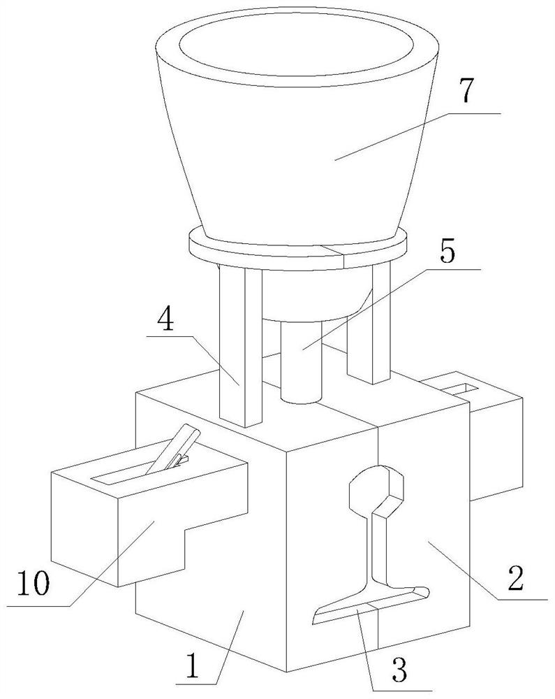
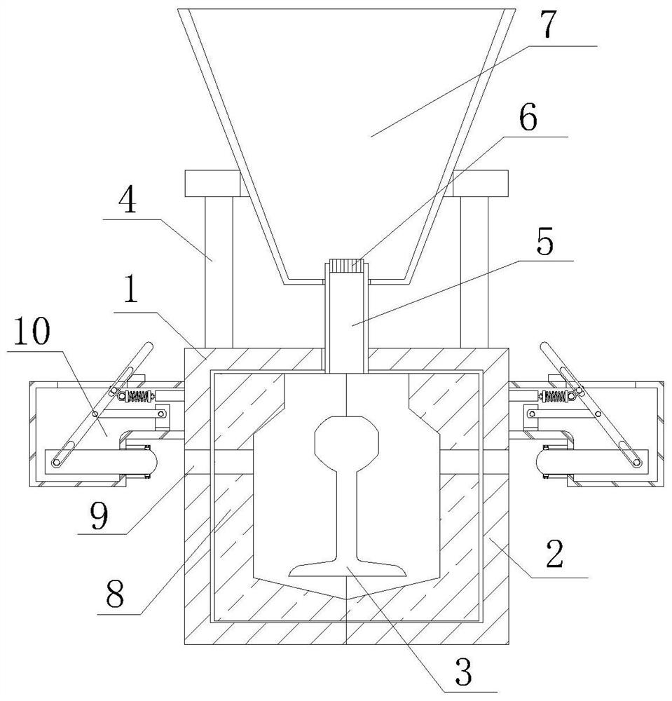
[0030] see figure 1 and figure 2 , the present invention provides a high-efficiency track repair device for rail vehicles through improvement, including a first mold 1 and an anti-blocking device 10, the right side of the first mold 1 is attached to the second mold 2, and the first mold 1 There are mold holes 3 in the middle of the front and rear sides of the second mold 2, the upper ends of the first mold 1 and the second mold 2 are fixedly connected with the receiving frame 4, and the middle part of the upper end of the second mold 2 is fixedly connected with the flow pipe 5, the receiving frame 4. A crucible 7 is installed on the upper end, and the lower end of the crucible 7 is plugged and fixed with the flow pipe 5. The upper end of the flow pipe 5 is provided with a soil cover 6. Both the first mold 1 and the second mold 2 are equipped with a sand mold 8, and the first mold The left side of 1 and the right side of the second mold 2 are both provided with a discharge po...

Embodiment 2

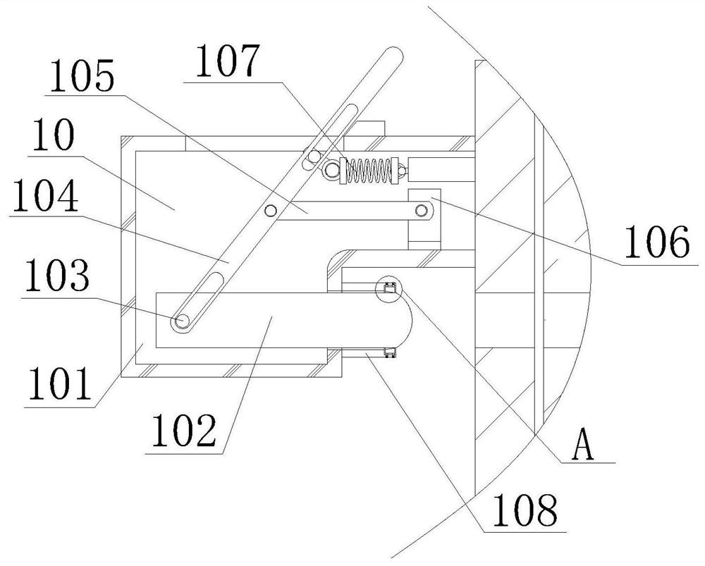
[0035] The present invention provides a high-efficiency track repair device for rail vehicles through improvement. A receiving block is provided on one side of the upper end of the housing 101, and a buffer layer is provided at the contact between the receiving block and the pull rod 104 on the housing 101, so that reset can be avoided. When the speed is too fast and damage occurs, the insertion shaft 1084 and the clip spring 1085 are arranged oppositely along the upper and lower sides of the rejecting ring 1083, and the overall elastic force of the clip spring 1085 is 2.5N, so that the elastic force of the clip spring 1085 ensures that the rejecting ring 1083 and the ejector rod 102 fit.

[0036] The present invention provides a kind of high-efficiency track repair device for rail vehicle through improvement, and its working principle is as follows;

[0037] First, first put the first mold 1 and the second mold 2 into the sand mold 8, and then place the first mold 1 and the s...


PUM


Abstract

The invention discloses an efficient rail repairing device for a rail vehicle. The device comprises a first mold and anti-blocking devices. According to the rail repairing device, the anti-blocking devices are arranged on the left side and the right side of the first mold and a second mold correspondingly, pull rods are pulled outwards to enable connecting rods to move, and ejector rods are drivento be inserted into discharging openings to conduct dredging movement under the cooperation of auxiliary rods, so that advantages of dredging the discharging openings and ensuring the discharging efficiency are achieved, reset mechanisms are arranged on the right sides of the upper ends of the pull rods, when the pull rods are pulled, sliding blocks arranged at the upper ends of the pull rods stretch tension springs, then when the pull rods are pulled, the tension springs pull back to drive the pull rods to reset, advantages of automatic reset of the pull rods and usability enhancement are achieved, by arranging removing mechanisms on the right sides of the lower ends of shells, when the ejector rods move back and return, removing rings in mounting grooves in one sides of connecting pipescan clean the ejector rods, molten metal is prevented from being attached to the outer portions of the ejector rods, and then beneficial effects of cleaning the outer surfaces of the ejector rods andguaranteeing usability of the ejector rods are achieved.

Description

technical field [0001] The invention relates to the related field of track repair, in particular to an efficient track repair device for rail vehicles. Background technique [0002] Rail vehicles are the main means of transportation for construction departments such as railway equipment maintenance, overhaul, and infrastructure construction. Rail vehicles are divided into heavy and light types. Those that can be withdrawn from the line by passengers at any time are called light rail vehicles; Those withdrawn from the line are called heavy-duty rail cars, and the track repair device is to repair the damaged track. At present, the repair of the track is carried out by aluminothermic welding for quick repair activities, and the weldment joints with appropriate gaps will be left. Assembled in a special mold, when the joint is preheated to a certain temperature, the high-temperature liquid metal formed by the reaction of the hot agent is injected into the mold to melt the metal o...

Claims


Application Information

Patent Timeline
Patent Type & Authority Applications(China)
IPC IPC(8): E01B31/18E01B31/02
CPCE01B31/02E01B31/18
Inventor 邱朝兴
Owner 邱朝兴
Why Eureka
Try Eureka