Electronic auxiliary equipment capable of efficiently dissipating heat

An auxiliary equipment and electronic technology, which is applied to the structural parts of electrical equipment, dispersed particle separation, electrical components, etc., can solve the problems of reducing the amount of air ingress, the dust cannot be collected and cleaned well, and the heat is easy to accumulate. The effect of improving heat dissipation efficiency

Inactive Publication Date: 2020-12-11
YUHUAN RUIJIANG COMPUTER CO LTD
View PDF0 Cites 3 Cited by
  • Summary
  • Abstract
  • Description
  • Claims
  • Application Information

AI Technical Summary

Problems solved by technology

[0002] In our daily life, we often use electronic products. In recent years, electronic products have developed faster and faster. When electronic products are used, they will generate a lot of heat. In order to dissipate heat, a radiator is usually installed. The structure of the radiator is generally very Simple, it mainly includes two parts: the fan and the radiator. The fan generates negative pressure through the rotation of the blades, extracts the hot air inside the equipment, and then discharges it to the outside. The radiator absorbs part of the heat, and the heat is easy to accumulate, and the fan is used for a long time Finally, the dust will accumulate on the dustproof net, reducing the air intake, resulting in poor heat dissipation performance, and the dust cannot be collected and cleaned well. An electronic auxiliary device capable of efficiently dissipating heat explained in the present invention can solve the above problems

Method used


Image

  • Electronic auxiliary equipment capable of efficiently dissipating heat
  • Electronic auxiliary equipment capable of efficiently dissipating heat
  • Electronic auxiliary equipment capable of efficiently dissipating heat

Examples


Embodiment Construction

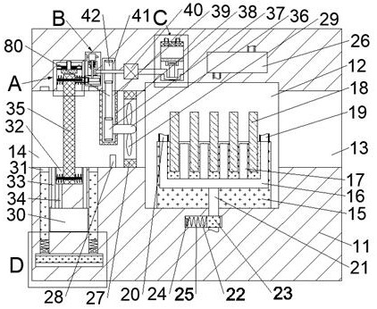
[0019] Combine below Figure 1-5 The present invention is described in detail, wherein, for the convenience of description, the orientations mentioned below are defined as follows: figure 1 The up, down, left, right, front and back directions of the projection relationship itself are the same.

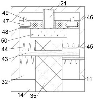
[0020] An electronic auxiliary device capable of efficiently dissipating heat according to the present invention includes a body 11, a heat dissipation chamber 12 is provided inside the body 11, and an outlet is connected between the right wall of the heat dissipation chamber 12 and the right end surface of the body 11. An air outlet 13, an air inlet 14 is communicated between the left wall of the heat dissipation chamber 12 and the left end surface of the body 11, and a heat dissipation base 15 is fixed on the lower wall of the heat dissipation chamber 12, and a heat dissipation base 15 is fixed inside the heat dissipation base 15. The upper ends of the main cooling pipes 16 communic...


PUM


Abstract

The invention discloses electronic auxiliary equipment capable of efficiently dissipating heat, and the equipment comprises a machine body, wherein a heat dissipation cavity is formed in the machine body, an air outlet is formed between the right wall face of the heat dissipation cavity and the right end face of the machine body in a communicating mode, and an air inlet is formed between the leftwall face of the heat dissipation cavity and the left end face of the machine body in a communicating mode; a heat dissipation base is fixedly arranged on the lower wall face of the heat dissipation cavity, a main cooling pipeline communicating with the upper end face is fixedly arranged in the heat dissipation base, and four evenly-distributed branch cooling pipes are arranged on the upper side of the main cooling pipeline located in the heat dissipation base in a communicating mode. By means of water cooling and air cooling, heat dissipation treatment of the electronic equipment is achieved;meanwhile, dust is prevented from entering the equipment through the dustproof net; dust accumulated on the dustproof net is treated in time, so the situation that the heat dissipation function is affected due to dust blockage is effectively prevented, the heat dissipation efficiency is improved, and the situation that the service life is shortened due to the fact that electronic elements are overheated is avoided.

Description

technical field [0001] The invention relates to the field of electronic radiators, in particular to electronic auxiliary equipment capable of efficiently dissipating heat. Background technique [0002] In our daily life, we often use electronic products. In recent years, electronic products have developed faster and faster. When electronic products are used, they will generate a lot of heat. In order to dissipate heat, a radiator is usually installed. The structure of the radiator is generally very Simple, it mainly includes two parts: the fan and the radiator. The fan generates negative pressure through the rotation of the blades, extracts the hot air inside the equipment, and then discharges it to the outside. The radiator absorbs part of the heat, and the heat is easy to accumulate, and the fan is used for a long time Finally, the dust will accumulate on the dustproof net, reducing the air intake, resulting in poor heat dissipation performance, and the dust cannot be coll...

Claims


Application Information

Patent Timeline
Patent Type & Authority Applications(China)
IPC IPC(8): H05K7/20B01D46/10B01D46/42
CPCH05K7/20218H05K7/20136H05K7/20181H05K7/20209B01D46/10B01D46/42B01D46/69
Inventor 李贞长
Owner YUHUAN RUIJIANG COMPUTER CO LTD
Why Eureka
Try Eureka