Transformer coil winding device
A transformer coil and winding device technology, which is applied in the direction of inductance/transformer/magnet manufacturing, coil manufacturing, electrical components, etc., can solve the problems of transformer performance degradation, waste of manpower, transformer scrapping, etc., and achieve uniform winding and good practicability , prevent loose effect
- Summary
- Abstract
- Description
- Claims
- Application Information
AI Technical Summary
Problems solved by technology
Method used
Image
Examples
Embodiment 1
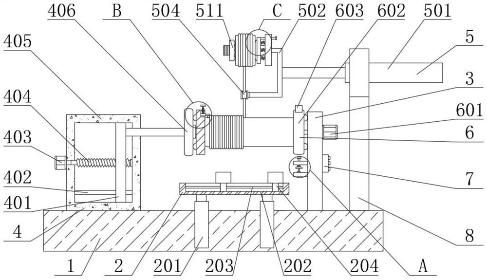
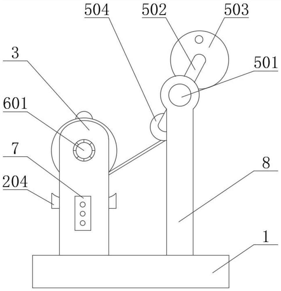
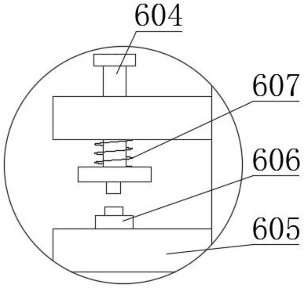
[0029] see Figure 1-7 , the present invention provides a technical solution:
[0030] A transformer coil winding device, comprising a base 1, a side plate 3 fixedly connected to the top of the base 1, and a support ring 8 fixedly connected to the top of the base 1, characterized in that the support ring 8 is arranged on the right rear side of the side plate 3, and the side The right end of the plate 3 is fixedly connected with a controller 7, and the side plate 3 is provided with a rotating circle recording mechanism 6, which can realize accurate counting of the number of turns, and the rotating circle recording mechanism 6 includes a fixed plate 605 and a second motor 601, the inside of the fixed plate 605 on the upper side is slidingly connected with a push rod 604, and the outside of the push rod 604 is provided with a second spring 607, and the two ends of the second spring 607 are respectively connected to the bottom end of the fixed plate 605 on the upper side and The ...
Embodiment 2
[0034] Workflow: in embodiment 2, the same part as embodiment 1 will not be repeated. The difference is that when feeding, turn the lifting screw 901, and the lifting screw 901 can move upward. When the lifting screw 901 moves upward, The lifting screw 901 will drive the telescopic plate 902 to move upwards, one end of the coil 506 will be sent away, the first electric telescopic rod 201 will stretch, the support plate 204 will approach the lower side of the iron rod, and the first motor 403 will drive the first screw rod 404 to rotate. The first screw rod 404 drives the outer slide plate 401 to move to the left, wherein the second stop rod 400 provided acts as a limit, which can increase the stability of the slide plate 401 when it moves. When the slide plate 401 moves to the left, Slide plate 401 drives top plate 406 to move to the left, and top plate 406 drives left splint 407 to move to the left, and at this moment, iron rod can move downward under the effect of gravity, an...
PUM
 Abstract
Description
Claims
Application Information
 - R&D
- Intellectual Property
- Life Sciences
- Materials
- Tech Scout
- Unparalleled Data Quality
- Higher Quality Content
- 60% Fewer Hallucinations
Browse by: Latest US Patents, China's latest patents, Technical Efficacy Thesaurus, Application Domain, Technology Topic, Popular Technical Reports.
© 2025 PatSnap. All rights reserved.Legal|Privacy policy|Modern Slavery Act Transparency Statement|Sitemap|About US| Contact US: help@patsnap.com


