
Flywheel

A technology of flywheels and hubs, applied to flywheels. It can solve the problems of easy fatigue of wheel hub, easy fatigue and damage of steel wire, etc., and achieve the effect of reducing fatigue loss and prolonging life

Pending Publication Date: 2020-12-11
深圳市中科超临技术有限公司
View PDF0 Cites 0 Cited by
  • Summary
  • Abstract
  • Description
  • Claims
  • Application Information

AI Technical Summary

Problems solved by technology

In the flywheels in the related art, the hubs are almost all circular hubs, and the steel wire rope is wound on the circular hub, requiring a large pre-tightening force to press the steel wire rope on the hub, and the large pre-tightening force causes the steel wire to be easily fatigued, and the hub Also prone to fatigue and damage

Method used


Image

  • Flywheel
  • Flywheel
  • Flywheel

Examples


Embodiment Construction

[0030] In order to facilitate the understanding of the present invention, the present invention will be described more fully below with reference to the associated drawings. Preferred embodiments of the invention are shown in the accompanying drawings. It should be noted that when a part is said to be "fixed" to another part, it can be directly on the other part or there can be an intervening part. When a section is said to be "connected" to another section, it may be directly connected to the other section or there may be intervening sections at the same time.

[0031] Unless otherwise defined, all technical and scientific terms used herein have the same meaning as commonly understood by one of ordinary skill in the technical field of the invention. The terms used herein in the description of the present invention are only for the purpose of describing specific embodiments, and are not intended to limit the present invention.

[0032] Flywheel energy storage refers to the e...


PUM


Abstract

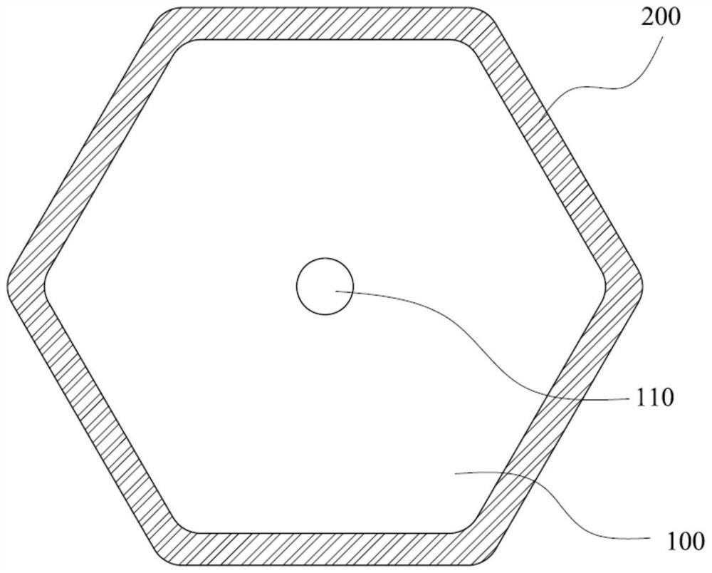
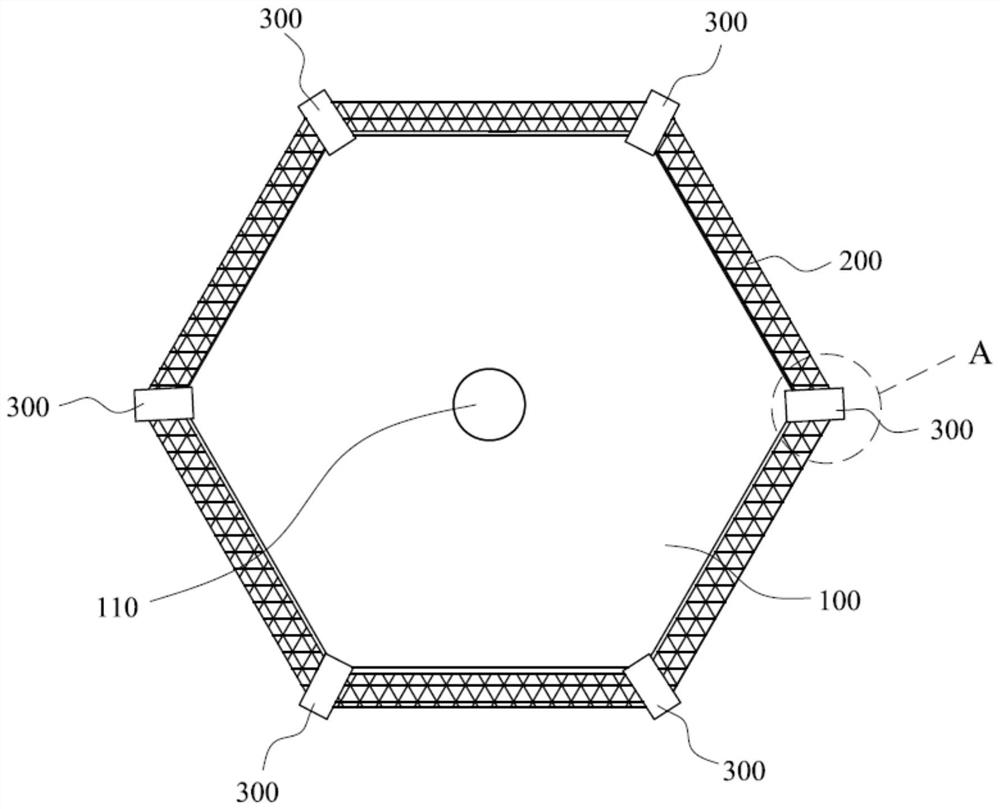
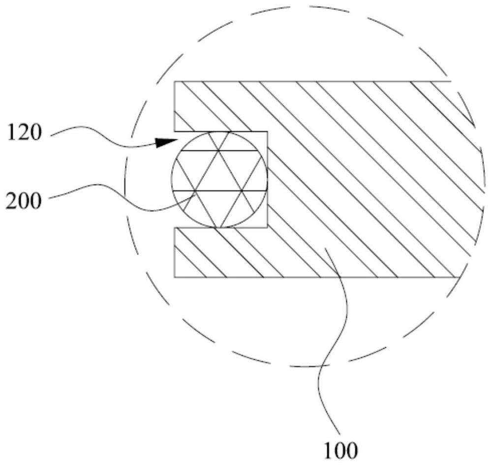
The invention discloses a flywheel, and belongs to the technical field of flywheel energy storage. The flywheel is designed for solving the problem that a flywheel hub is prone to fatigue damage. Theflywheel comprises a polygonal hub and a flywheel outer ring, and the flywheel outer ring is arranged around the polygonal hub and connected with the polygonal hub. The flywheel outer ring of the flywheel can be connected with top points of the polygonal hub through fasteners, so that the flywheel outer ring can be fixed to the polygonal hub with very small pre-tightening force; and when the flywheel rotates, the part, between two connecting points of the flywheel outer ring and the polygonal hub, of the flywheel outer ring is separated from the polygonal hub along with centrifugal force, so that the fatigue loss of the hub is reduced, and the service life of the flywheel is prolonged advantageously.

Description

technical field [0001] The invention relates to the technical field of flywheel energy storage, in particular to a flywheel. Background technique [0002] Flywheel energy storage device is a kind of energy storage device for electromechanical energy conversion, which has broad application prospects. Among them, the flywheel is the core component of the flywheel energy storage system. In the flywheels in the related art, the hubs are almost all circular hubs, and the steel wire rope is wound on the circular hub, requiring a large pre-tightening force to press the steel wire rope on the hub, and the large pre-tightening force causes the steel wire to be easily fatigued, and the hub Also prone to fatigue and damage. Contents of the invention [0003] The purpose of the present invention is to propose a flywheel capable of reducing hub fatigue loss. [0004] For reaching this purpose, the present invention adopts following technical scheme: [0005] A flywheel comprises a ...

Claims


Application Information

Patent Timeline
IPC IPC(8): F16F15/30
CPCF16F15/30
Inventor 王亚骏孙海翔古小文窦新国王定雪王林朱重庆齐阳江凌云李宜康李聪李南张航张腾涛刘烜赫周毅文郑监林杨宪辉陈昱江戴志鸿
Owner 深圳市中科超临技术有限公司
Learn More