
Casing structure and rotor and stator structure comprising same

A technology of rotating stator structure and casing, applied in mechanical equipment, machine/engine, liquid fuel engine, etc., can solve problems such as increasing airflow leakage loss, affecting compressor performance, deformation, etc.

Active Publication Date: 2020-12-11
AECC SHENYANG ENGINE RES INST
View PDF11 Cites 5 Cited by
  • Summary
  • Abstract
  • Description
  • Claims
  • Application Information

AI Technical Summary

Problems solved by technology

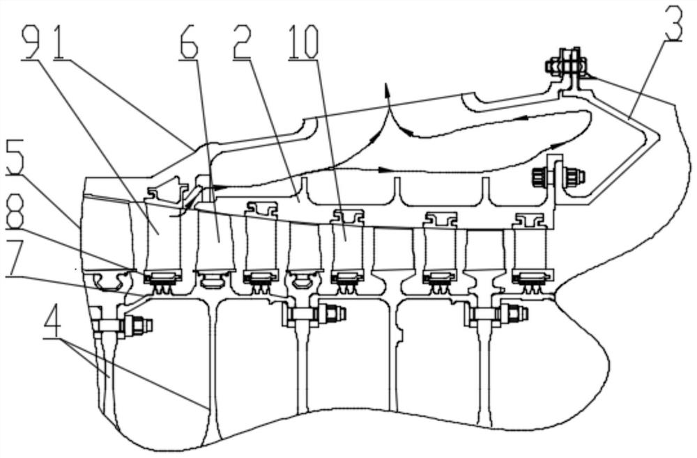
[0002] The rotor-stator structure of the compressor usually works under high temperature and high pressure. Under such working conditions, the casing is prone to deformation, and the gap between it and the rotor blades increases, which increases the leakage loss of the air flow at this place and affects the performance of the compressor. In addition, due to the large temperature and pressure gradients in the rotor-stator structure when the compressor is working, the rear section of the casing is subjected to large temperature and load, and the deformation is particularly serious, which has a more prominent impact on the performance of the compressor

Method used


Image

  • Casing structure and rotor and stator structure comprising same
  • Casing structure and rotor and stator structure comprising same

Examples


Embodiment Construction

[0034] In order to make the technical solution of the present application and its advantages clearer, the technical solution of the present application will be further clearly and completely described in detail below in conjunction with the accompanying drawings. It can be understood that the specific embodiments described here are only part of the application Examples are only used to explain the present application, not to limit the present application. It should be noted that, for the convenience of description, only the parts related to the present application are shown in the drawings, and other relevant parts can refer to the general design. In the case of no conflict, the embodiments in the application and the technologies in the embodiments Features can be combined with each other to obtain new embodiments.

[0035] In addition, unless otherwise defined, the technical terms or scientific terms used in the description of the application shall have the usual meanings und...


PUM


Abstract

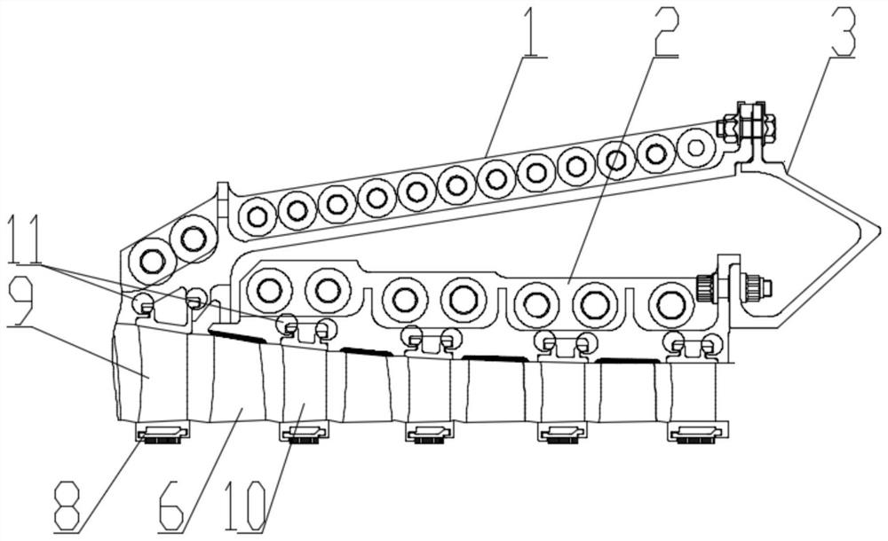
The invention belongs to the technical field of structural designs of rotor and stator structures of compressors, and particularly relates to a casing structure; the casing structure comprises an outer casing and an inner casing, wherein the inner casing is arranged at the inner side of the outer casing and located at the rear section of the outer casing; and an annular air gap is formed between the inner casing and the outer casing. In addition, the invention relates to a rotor and stator structure comprising the casing structure.

Description

technical field [0001] The application belongs to the technical field of compressor rotor-stator structure design, and in particular relates to a casing structure and its rotor-stator structure. Background technique [0002] The rotor-stator structure of the compressor usually works under high temperature and high pressure. Under such working conditions, the casing is prone to deformation, and the gap between it and the rotor blades increases, which increases the leakage loss of the air flow at this place and affects the performance of the compressor. In addition, due to the large temperature and pressure gradients in the rotor-stator structure when the compressor is working, the rear section of the casing is subjected to large temperature and load, and the deformation is particularly serious, which has a more prominent impact on the performance of the compressor. [0003] In view of the existence of above-mentioned technical defect, propose this application. [0004] It sh...

Claims


Application Information

Patent Timeline
Patent Type & Authority Applications(China)
IPC IPC(8): F04D29/40F04D29/26
CPCF04D29/403F04D29/26
Inventor 姜永强印雪梅王华韩方军
Owner AECC SHENYANG ENGINE RES INST
Learn More