A solid wood chair scraping device for furniture processing
A technology for solid wood chairs and furniture, applied in wood processing appliances, manufacturing tools, forming/shaping machines, etc., can solve the problems of cumbersome operation process, labor-intensive, low work efficiency, etc., to achieve simple operation, improve work efficiency, and save manpower Effect
- Summary
- Abstract
- Description
- Claims
- Application Information
AI Technical Summary
Problems solved by technology
Method used
Image
Examples
Embodiment 1
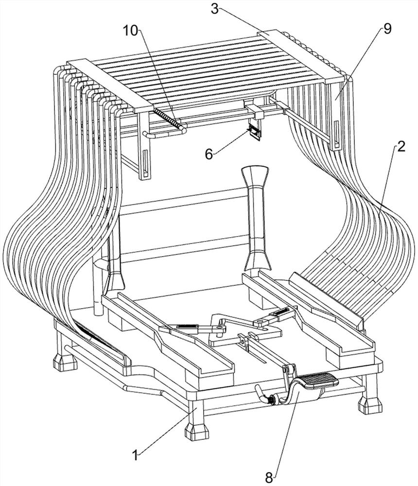
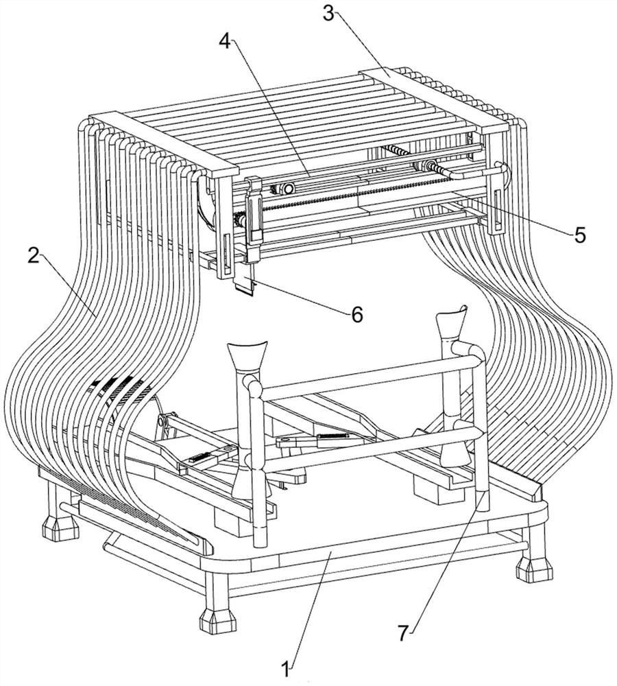
[0030] A solid wood chair scraping device for furniture processing, such as Figure 1-6 As shown, it includes a base 1, a support frame 2 and a mounting plate 3, the top of the base 1 is connected with a support frame 2, the left and right sides of the top of the support frame 2 are connected with a mounting plate 3, and a guide assembly 4, a walking mechanism 5, The scraping assembly 6 and the positioning assembly 7 are provided with a guide assembly 4 between the mounting plates 3 on both sides. The guide assembly 4 is provided with a traveling mechanism 5 and a scraping assembly 6 .
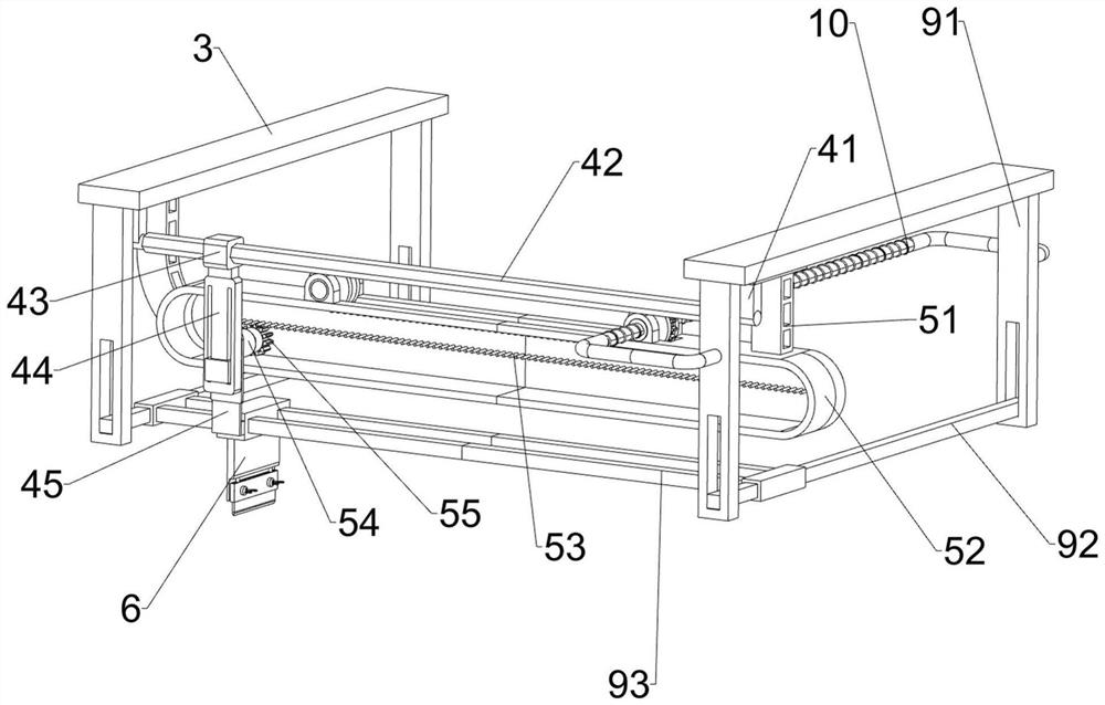
[0031] The guide assembly 4 includes a connecting seat 41, a guide rod 42, a slider 43, a connecting guide plate 44 and a lifting slide plate 45. The bottoms of the mounting plates 3 on both sides are slidably connected with the connecting seat 41, and the connecting seats 41 on both sides are connected with a guide rail. The rod 42 is slidably connected with a slide block 43 on the guide bar ...
Embodiment 2
[0037] On the basis of Example 1, such as Figure 4 As shown, there is also a stopper assembly 8, and the stopper assembly 8 includes a triangular plate 81, a U-shaped frame 83, a pedal 84, a torsion spring 85, a connecting rod 86, a guide sleeve 87, an inclined plane baffle plate 88 and a second return spring 89 , a triangular plate 81 is slidingly connected in the middle of the top of the base 1, a V-shaped groove 82 is opened on the triangular plate 81, a U-shaped frame 83 is connected to the front side of the base 1, and a pedal 84 is rotatably connected to the U-shaped frame 83, and the pedal 84 is connected to the U-shaped frame. A torsion spring 85 is connected between the frame 83, a connecting rod 86 is hingedly connected to the front side of the triangular plate 81, the connecting rod 86 is hingedly connected to the pedal 84, and a guide sleeve 87 is connected to the middle part of the side where the support plates 71 on both sides are close to each other. An incline...
Embodiment 3
[0040] On the basis of Example 2, such as image 3 As shown, also include stabilizing component 9, and stabilizing component 9 comprises riser 91, elevating bar 92 and guide frame 93, both sides of front and back of mounting plate 3 bottoms are all connected with riser 91, and the riser 91 bottoms of front and back both sides Lifting rods 92 are slidably connected between the two lifting rods 92, and a guide frame 93 is slidably connected between the two lifting rods 92, and the guide frame 93 is slidably matched with the guide block 61.
[0041] The guide block 61 can slide on the guide frame 93 when moving, so that the guide block 61 moves more stably.
[0042] Such as Figure 7 As shown, a transposition assembly 10 is also included. The transposition assembly 10 includes a screw rod 101, a pulley 102 and a toothed belt 103. A screw rod 101 is connected between the two vertical plates 91 on the left side. The left and right sides of the top of the walking guide rail 52 Pul...
PUM
 Abstract
Description
Claims
Application Information
 - R&D Engineer
- R&D Manager
- IP Professional
- Industry Leading Data Capabilities
- Powerful AI technology
- Patent DNA Extraction
Browse by: Latest US Patents, China's latest patents, Technical Efficacy Thesaurus, Application Domain, Technology Topic, Popular Technical Reports.
© 2024 PatSnap. All rights reserved.Legal|Privacy policy|Modern Slavery Act Transparency Statement|Sitemap|About US| Contact US: help@patsnap.com


