A Distributed Annular Gap Ejector Device

An ejector and distributed technology, applied in the direction of injection devices, liquid injection devices, etc., can solve the problems of long mixing section, low ejection efficiency, and poor uniformity of mixed fluid, so as to reduce installation space requirements and improve ejection efficiency. The effect of high efficiency and ejection efficiency

Active Publication Date: 2021-06-22
INST OF HIGH SPEED AERODYNAMICS OF CHINA AERODYNAMICS RES & DEV CENT
View PDF17 Cites 0 Cited by
  • Summary
  • Abstract
  • Description
  • Claims
  • Application Information

AI Technical Summary

Problems solved by technology

The annular seam ejector is a relatively classic ejector, but the traditional annular seam ejector has the following disadvantages: first, the energy and material exchange area between the high-energy fluid and the low-energy fluid is not large, and the ejection efficiency is low; second, the high-energy fluid The mixing speed with low-energy fluid is slow, the required mixing section is long, and the uniformity of the mixed fluid is poor; the third is that the ejector has a large size, expensive manufacturing and processing costs, and complex space installation requirements

Method used


Image

  • A Distributed Annular Gap Ejector Device
  • A Distributed Annular Gap Ejector Device

Examples


Embodiment 1

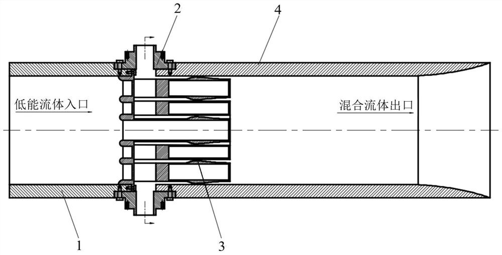
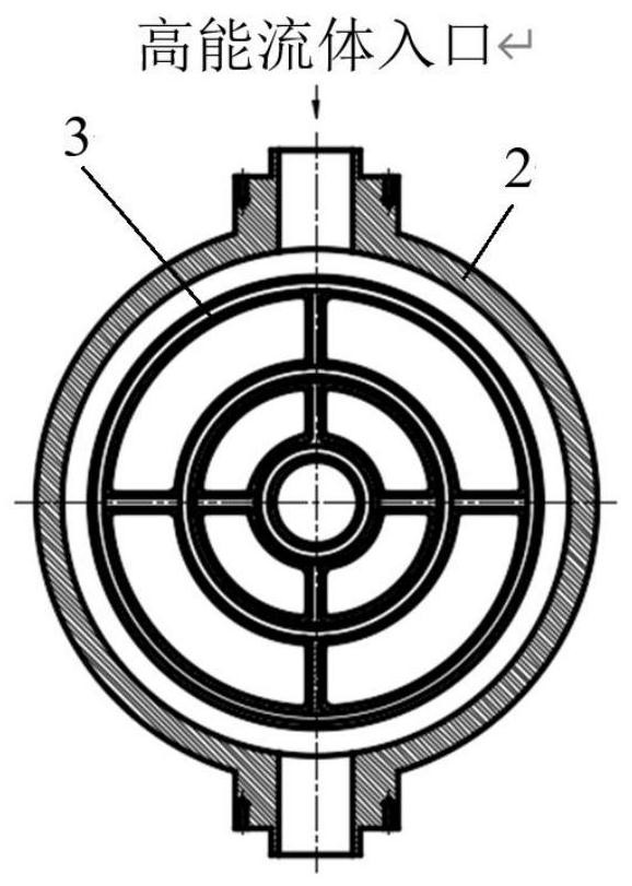
[0037] The number of nozzle unit bodies in this embodiment is 3, each nozzle unit body is provided with an axisymmetric binary semi-nozzle pipe, and each nozzle unit body is connected from the inner ring to the outer ring by 4 centrally symmetrical nozzles. The hollow type reinforcing rib is connected and supported; the annular cavity communicated with each nozzle unit body is also arranged in the binary annular slit ejector 3, and the high-energy fluid enters the annular cavity from the through hole of the high-energy fluid inlet section 2 and flows from the The outlet of the nozzle unit body sprays out.

[0038] The numerical simulation results show that, compared with the traditional annular seam ejector, the distributed annular seam ejector device of this embodiment requires less space under the premise of achieving the same ejection effect. Specifically, the diameter of the pipe section can be It can be reduced by more than 30%, and the length of the pipe section can be r...


PUM


Abstract

The invention discloses a distributed circular seam ejector device. The device adopts a pipeline connection method, which includes sequentially connected low-energy fluid inlet section, high-energy fluid inlet section and mixed fluid outlet section; the binary annular ejector is installed in the pipeline near the high-energy fluid inlet section; the surface of the high-energy fluid inlet section The through hole is connected with the external high-pressure tank; the low-energy fluid inlet section, the high-energy fluid inlet section and the mixed fluid outlet section are concentric with the central axis; The pipe units are connected by reinforcing ribs, and some of the reinforcing ribs are hollow. The high-energy fluid enters the nozzle unit body from the through hole of the high-energy fluid inlet section and sprays out from the outlet; the nozzle unit body is provided with an annular nozzle. The device is suitable for fluid ejection control of gas and liquid. The device improves the ejection efficiency, reduces the outer dimension of the ejector device, and reduces the space installation requirement of the ejector device.

Description

technical field [0001] The invention belongs to the technical field of flow control, and in particular relates to a distributed circular seam ejector device. Background technique [0002] Fluid is a general term for gas and liquid. Most fluids, such as oil, water and air, are indispensable substances for people's life, production and scientific research. The flow speed of the fluid varies from fast to slow, and people often hope to inject low-energy fluid through high-energy fluid to increase the velocity of low-energy fluid and increase the flow rate of low-energy fluid. [0003] In general life and production activities, people do not have high requirements for the flow speed of fluids, such as tap water, gas stations, gas stations, heating and natural gas, etc., only need a certain flow speed and flow rate to meet the requirements. However, in scientific research, people often need to efficiently eject low-energy fluids through high-energy fluids. In power plants, fuel ...

Claims


Application Information

Patent Timeline
Patent Type & Authority Patents(China)
IPC IPC(8): B05B7/04
CPCB05B7/04
Inventor 李方吉张林樊建超赵清毛代勇苏北辰王志宾于志松郭民李为群
Owner INST OF HIGH SPEED AERODYNAMICS OF CHINA AERODYNAMICS RES & DEV CENT
Why Eureka
Try Eureka