Novel power equipment box

A power equipment box, a new type of technology, applied in electrical components, substation/switch layout details, cooling/ventilation of substation/switchgear, etc.

Inactive Publication Date: 2020-12-08
张明
View PDF0 Cites 2 Cited by
  • Summary
  • Abstract
  • Description
  • Claims
  • Application Information

AI Technical Summary

Problems solved by technology

[0002] Power equipment mainly includes two parts: power generation equipment and power supply equipment. The power equipment box is the final equipment of the power supply equipment system, which is used to provide protection, monitoring and control for the load. The existing power equipment box connects The current is transmitted to the electrical equipment, because the transmission line will inevitably generate resistance, and heat will be generated when the current passes through the resistance, especially when the external load is high, it will generate high heat, so if the power equipment box is used at the same time In a high temperature environment, the internal temperature will be very high, and it is easy to melt or even burn the paint of the cables installed inside for the connection of electronic components, destroying the internal components of the power equipment box and causing an open circuit, and some power equipment boxes The internal wiring method uses a series connection method, so when a certain terminal is disconnected, the entire power equipment box will lose its working ability

Method used


Image

  • Novel power equipment box
  • Novel power equipment box
  • Novel power equipment box

Examples


specific Embodiment

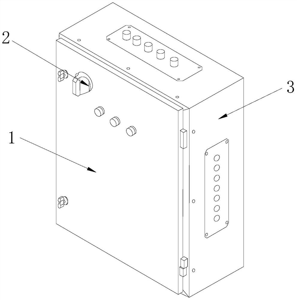
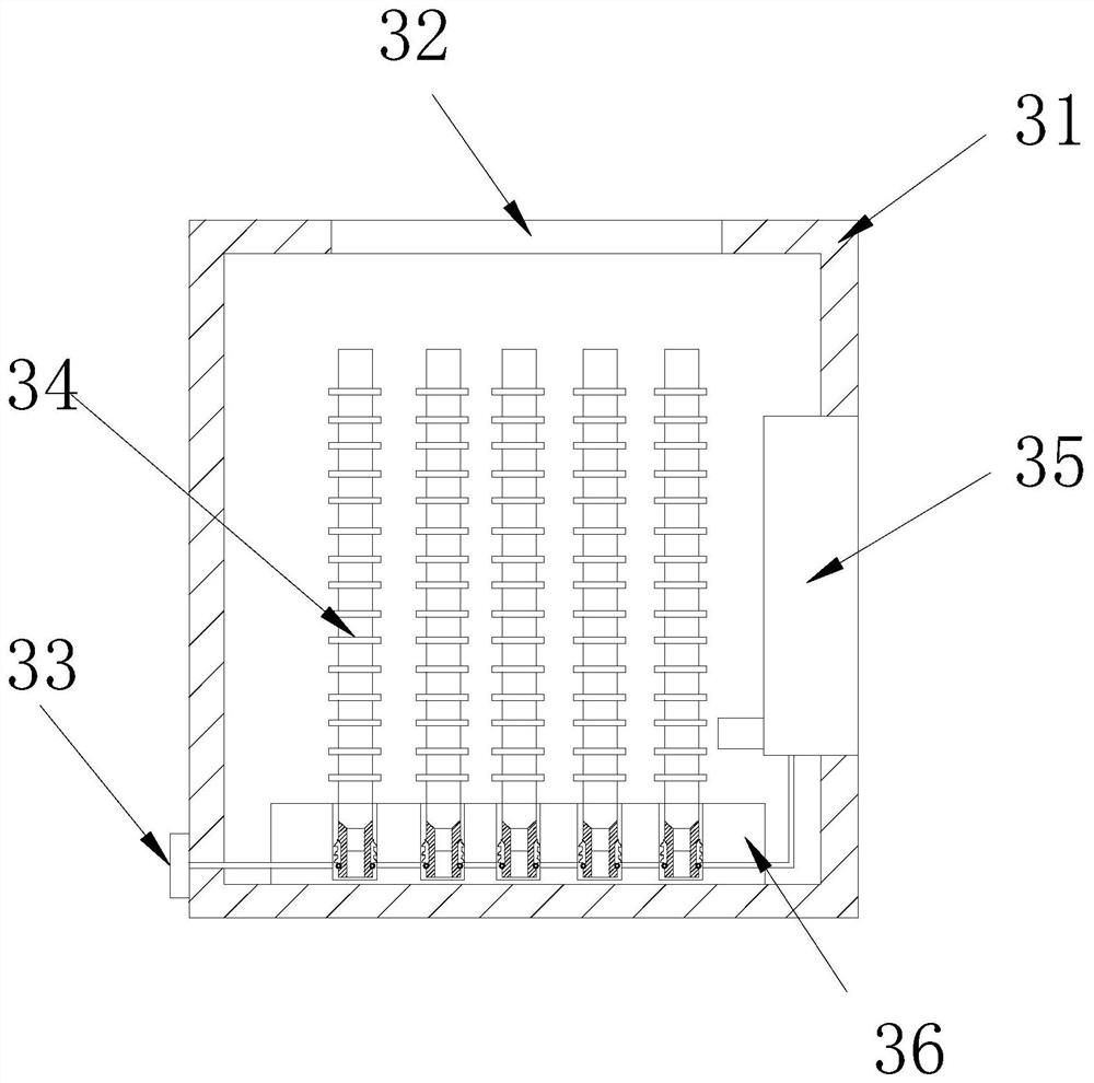
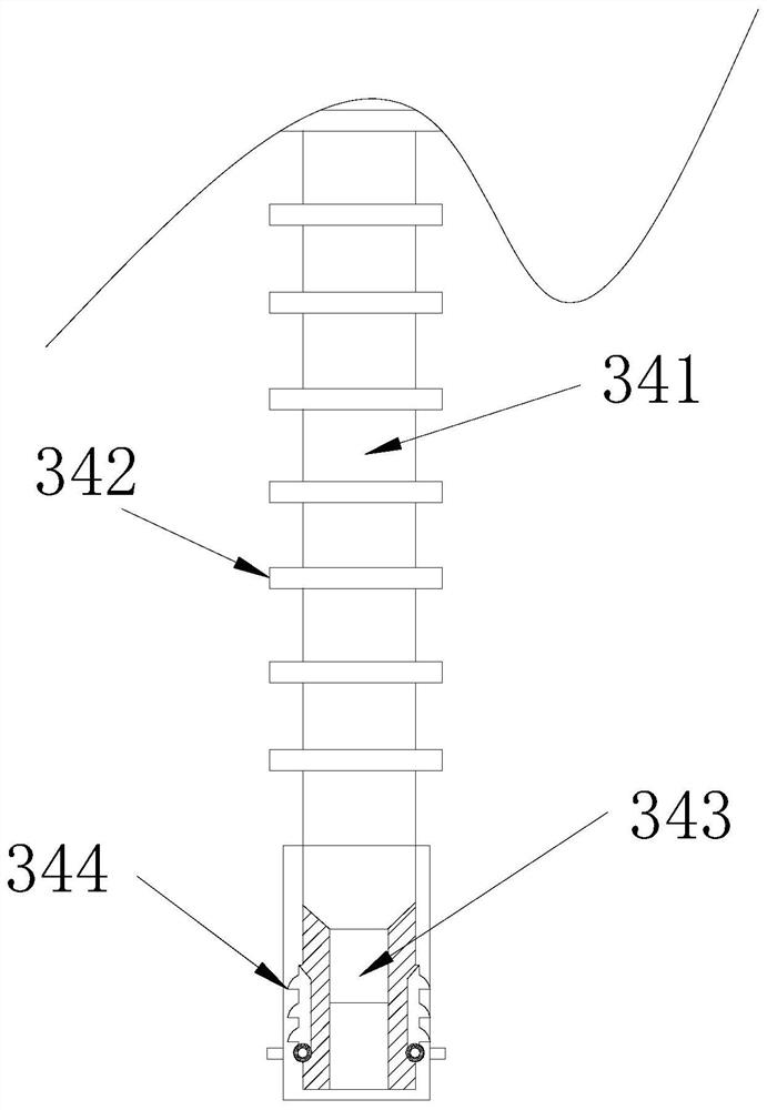
[0024] see Figure 1-Figure 5 , the specific embodiments of the present invention are as follows: a new type of electric equipment box, its structure includes a box cover 1, a control button 2, and a box body 3, one side of the box cover 1 is hingedly connected to the front of the box body 3, and the control button 2 The back side is movably engaged with the front side of the box cover 1; the box body 3 includes a casing 31, a cooling plate 32, a power connection port 33, a power connection pole 34, a cooler 35, and a power connection seat 36; 32, the outer layer is welded and connected, the right side of the power connection port 33 is fixedly installed on the left side of the housing 31, the bottom of the power connection rod 34 is superposed with the top of the power connection seat 36, and the outer layer of the cooler 35 is fixedly installed On the right side of the shell 31, the bottom of the socket 36 is welded to the bottom of the shell 31. There are multiple poles 34 ...

Embodiment 2

[0030] see Figure 6-Figure 7The specific embodiment of the present invention is as follows: the cooler 35 includes an isolation shell 351, an air inlet 352, a temperature sensor 353, a blower 354, a semiconductor refrigerator 355, a fairing 356, and a dust cover 357. The right side of the isolation shell 351 Formed integrally with the air inlet 352, the bottom of the temperature sensor 353 is fixedly installed inside the isolation case 351, the back of the blower 354 is fixedly installed inside the isolation case 351, and the back of the semiconductor refrigerator 355 overlaps with the inside of the isolation case 351 Together, the bottom of the fairing 356 is placed horizontally, the two ends of the dust cover 357 are welded to the left side of the isolation case 351, and the semiconductor cooler 355 adopts a TEC 1-12703 type semiconductor cooling chip, which is small in size and high in power. , which is conducive to installation in a relatively narrow space, while generati...


PUM


Abstract

The invention discloses a novel power equipment box. The power equipment box structurally comprises a box cover, a control button and a box body, one side of the box cover is hinged with the front surface of the box body, and the back surface of the control button is movably clamped with the front surface of the box cover. According to the invention, replacement devices are arranged at the bottomsof power connecting poles. When one of the connecting poles in the series-connected power equipment box is broken and pulled out, and pressure plates can be combined by boost rings, so that internalconductive wires can be reconnected, and the remaining power connecting poles can work normally. At the same time, the temperature inside the box can be automatically monitored at any time. When the temperature is too high, a cooler is automatically started to cool the interior of the box body, and the situation that internal electronic elements are damaged and cannot work normally due to high temperature generated by work or the external environment is avoided.

Description

technical field [0001] The invention relates to the field of electric equipment, in particular to a novel electric equipment box. Background technique [0002] Power equipment mainly includes two parts: power generation equipment and power supply equipment. The power equipment box is the final equipment of the power supply equipment system, which is used to provide protection, monitoring and control for the load. The existing power equipment box connects The current is transmitted to the electrical equipment, because the transmission line will inevitably generate resistance, and heat will be generated when the current passes through the resistance, especially when the external load is high, it will generate high heat, so if the power equipment box is used at the same time In a high temperature environment, the internal temperature will be very high, and it is easy to melt or even burn the paint of the cables installed inside for the connection of electronic components, destr...

Claims


Application Information

Patent Timeline
Patent Type & Authority Applications(China)
IPC IPC(8): H02B1/46H02B1/48H02B1/20H02B1/56
CPCH02B1/202H02B1/46H02B1/48H02B1/565
Inventor 张明
Owner 张明
Why Eureka
Try Eureka