


Quick Research
Generate reliable direction feasibility study reports for your R&D in just a few steps.

Technical Q&A
Discover and master advanced knowledge NOW. Basics, ideas, possibilities, all at once.

Find Solutions
As an expert in R&D theories, this can generate solutions to your technical problems instantly.

Evaluate Feasibility
Analyze your overall solution with one click, know your potential R&D risks in advance.

Monitor Landscape
Get weekly tech updates, stay abreast of the latest tech innovations and key insights.
Textile fabric drying equipment
A technology for drying equipment and textile fabrics, which is applied in the field of textile processing and can solve problems such as the inability to realize continuous drying of fabrics
- Summary
- Abstract
- Description
- Claims
- Application Information
AI Technical Summary
Problems solved by technology
Method used
Image

Examples
Embodiment 1
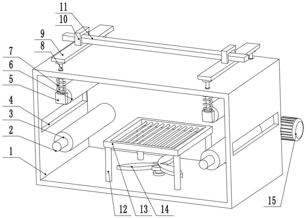
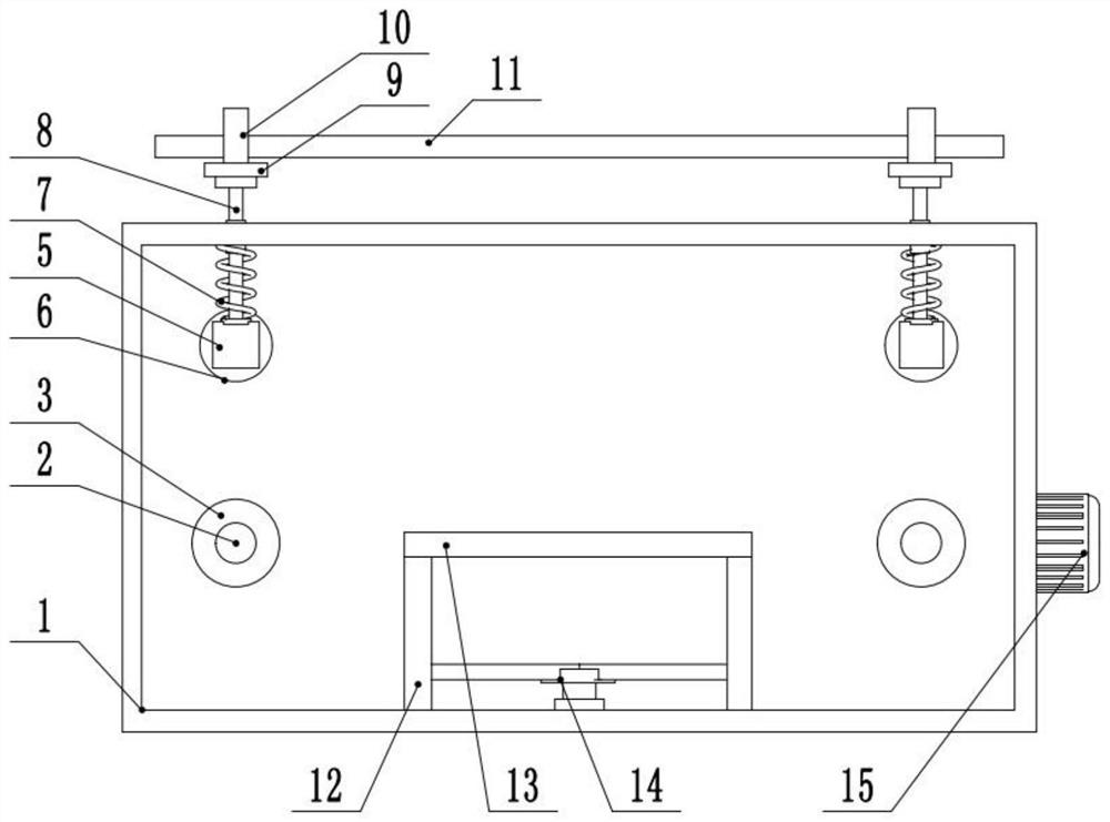
[0023] see Figure 1-3 , a drying equipment for textile fabrics, comprising a drying box 1, through holes 4 are provided on the left and right sides of the drying box 1, and a rotating shaft 2 is provided on the left and right sides of the rear side wall of the drying box 1, and the rotating shaft 2 The middle part is provided with a supporting roller 3, the top left and right sides of the drying box 1 are slidingly connected to the guide rod 8, the lower end of the guide rod 8 is fixedly connected to the fixed block 5, and the middle part of the fixed block 5 is connected to the pressure roller 6 and the fixed block 5 in rotation. A spring 7 is arranged between the drying box 1, and the spring 7 is sleeved on the outside of the guide rod 8. The top of the guide rod 8 is fixedly connected to the front and rear ends of the fixed plate 9, and the middle part of the fixed plate 9 is provided with a handle 10.
[0024] The rear side wall right end of described drying case 1 is pro...
Embodiment 2
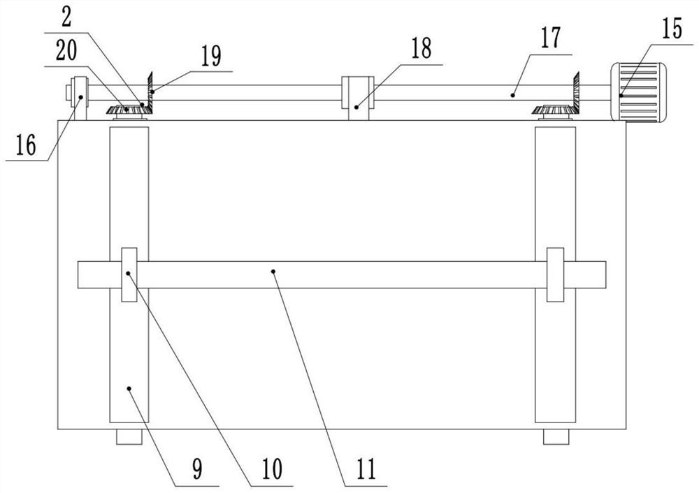
[0026] see figure 1 , the other content of this embodiment is the same as that of Embodiment 1, except that: the middle part of the handle 10 runs through the left and right ends of the connecting cross bar 11 . In order to allow the two pressure rollers 6 on the left and right sides to move up and down simultaneously, a cross bar 11 is set to be connected with the handles 10 on the left and right sides simultaneously. When the cross bar 11 moves up and down, it can simultaneously drive the two pressure rollers 6 on the left and right sides to move up and down.
[0027] During the implementation of the present invention, the fixed plate 9 is pulled upwards, and the fixed plate 9 pulls the pressure roller 6 to move upward through the guide rod 8, so that the pressure roller 6 is separated from the support roller 3. At this time, the cloth that needs to be dried will be free. The end passes through the left side of the drying box 1 and passes out from the right side of the dryi...
PUM
 Abstract
Description
Claims
Application Information
 - R&D Engineer
- R&D Manager
- IP Professional
- Industry Leading Data Capabilities
- Powerful AI technology
- Patent DNA Extraction
Browse by: Latest US Patents, China's latest patents, Technical Efficacy Thesaurus, Application Domain, Technology Topic, Popular Technical Reports.
© 2024 PatSnap. All rights reserved.Legal|Privacy policy|Modern Slavery Act Transparency Statement|Sitemap|About US| Contact US: help@patsnap.com