
Bolt fastening structure for railway engineering track laying

A technology for railway engineering and fastening structures, which is applied in the direction of railway fixtures, tracks, roads, etc., to achieve the effect of strengthening stability

Pending Publication Date: 2020-12-08
梁意常
View PDF4 Cites 2 Cited by
  • Summary
  • Abstract
  • Description
  • Claims
  • Application Information

AI Technical Summary

Problems solved by technology

[0004] Aiming at the deficiencies of the prior art, the present invention provides a bolt fastening structure for railway engineering track laying, which solves the problem that the U-shaped screw on the existing sleeper only squeezes and fixes the rail from top to bottom. There is no targeted front and rear positioning constraint force on the rail, and it is completely restricted by the extrusion friction of the U-shaped screw. When a small-scale deviation occurs between the rail and the sleeper, it is necessary to completely tighten the entire set of bolts. The problem of dismantling

Method used


Image

  • Bolt fastening structure for railway engineering track laying
  • Bolt fastening structure for railway engineering track laying
  • Bolt fastening structure for railway engineering track laying

Examples


Embodiment Construction

[0022] The following will clearly and completely describe the technical solutions in the embodiments of the present invention with reference to the accompanying drawings in the embodiments of the present invention. Obviously, the described embodiments are only some, not all, embodiments of the present invention. Based on the embodiments of the present invention, all other embodiments obtained by persons of ordinary skill in the art without making creative efforts belong to the protection scope of the present invention.

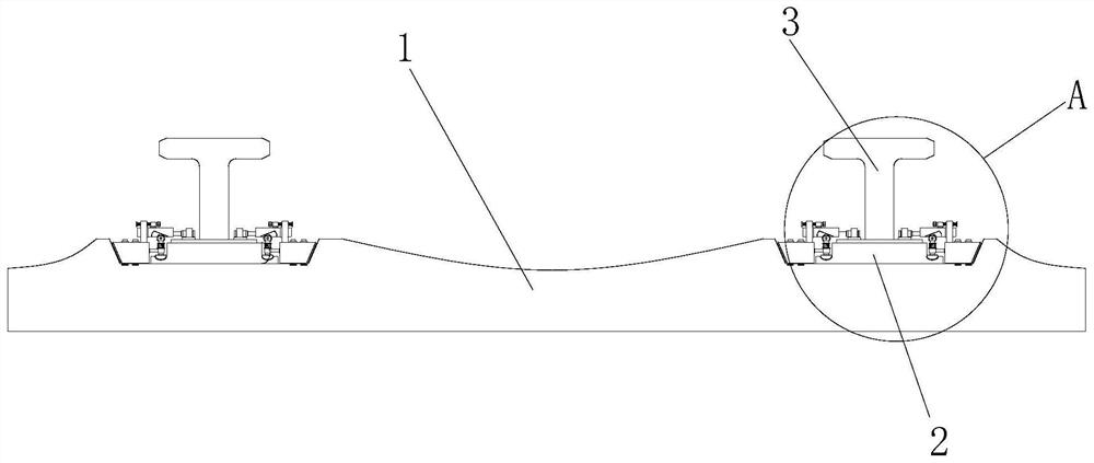
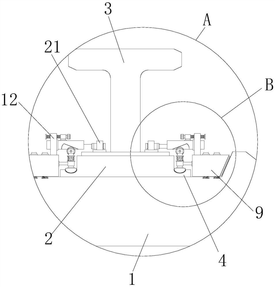
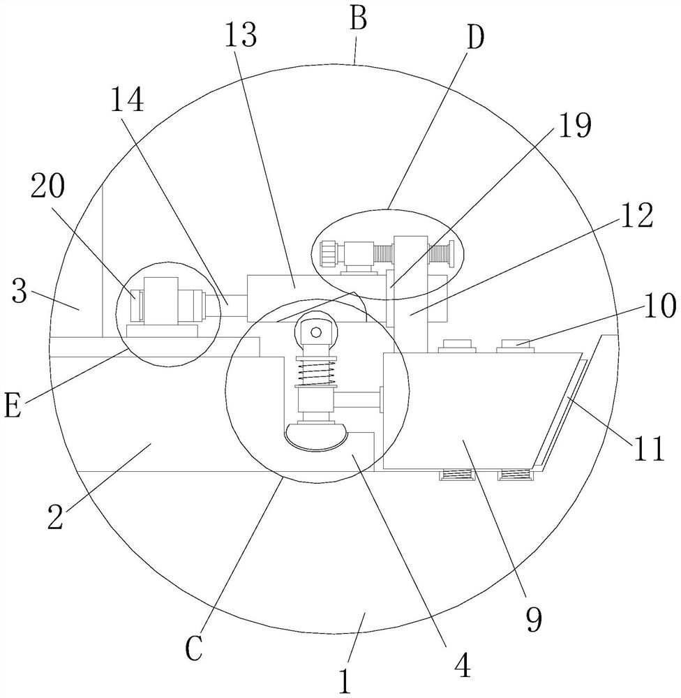
[0023] Such as Figure 1-6As shown, the present invention provides a technical solution: a bolt fastening structure for railway engineering track laying, including a plurality of sleepers 1, the tops of both sides of the sleeper 1 are provided with grooves, and rails are placed in the grooves of the sleeper 1 The force plate 2, the top of the rail force plate 2 is fixedly connected with the steel track 3, the two sides of the rail force plate 2 are fixedly con...


PUM


Abstract

The invention discloses a bolt fastening structure for railway engineering track laying. The bolt fastening structure comprises a plurality of sleepers, grooves are formed in the tops of the two sidesof the sleepers correspondingly, track stress plates are placed in the grooves of the sleepers, and steel tracks are fixedly connected to the tops of the track stress plates. According to the bolt fastening structure for railway engineering track laying, pull parts drive lock catches to move downwards to enable the lock catches to be connected to positioning pipes in a sleeving mode; then steel sliding push plates are driven to move horizontally through rotation of adjusting rods and the thread propelling principle, that is, the lock catches on the two sides of the steel tracks are pulled towards the outer sides to form a tightened state, and thus it is ensured that the two sides of the steel tracks are more stable; and the contact extrusion height between steel rollers and the steel sliding push plates is changed through the height displacement difference between inclined plane grooves in the bottoms of the steel sliding push plates, that is, adjustable extrusion abutting blocks arelocated in grooves of positioning plates, so that the track stress plates have part of displacement adjusting spaces so as to ensure that the steel tracks are fixed to the sleepers more accurately andstably.

Description

technical field [0001] The invention relates to the technical field of train track bolt fastening, in particular to a bolt fastening structure for railway engineering track laying. Background technique [0002] As an important part of the railway line, the track is an integral engineering structure. It consists of main components such as rails, sleepers, connecting parts, ballast beds, anti-climbing equipment and turnouts. The track is usually composed of two parallel rails, and the rails are fixed. Put it on the sleeper, under the sleeper is the ballast bed, and the connecting parts play a connecting role between the rail and the rail and between the rail and the sleeper. The main line tracks of my country's railways are divided into five types: extra heavy, heavy, sub-heavy, medium and light. One type, in which the sleeper is laid between the ballast bed and the rail to bear the force and vibration transmitted from the rail and to the ballast bed; at the same time, it is use...

Claims


Application Information

Patent Timeline
IPC IPC(8): E01B9/10E01B9/12E01B13/00
CPCE01B9/10E01B9/12E01B13/00E01B2201/04
Inventor 梁意常
Owner 梁意常
Learn More