
Single-connecting-rod type suspension structure with stable structure

A structurally stable, single-link technology, used in suspensions, elastic suspensions, interconnecting systems, etc., can solve the effect of affecting vehicle shock absorption and the effectiveness of shock absorption, large buffer stroke and rebound stroke, and affect the connecting rod. Normal rebound and other problems, to achieve the effect of good shock absorption, reduce the number of swings, and reduce mechanical wear

Inactive Publication Date: 2020-12-08
曹甲乐
View PDF0 Cites 0 Cited by
  • Summary
  • Abstract
  • Description
  • Claims
  • Application Information

AI Technical Summary

Problems solved by technology

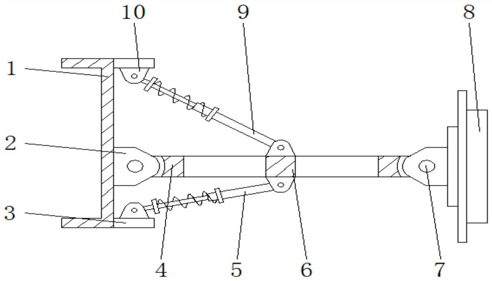
[0003] In the existing single-link suspension structure, since the shock absorber is only arranged above the suspension, in actual use, it will affect the normal rebound of the connecting rod, and the rebound buffer stroke and rebound stroke Larger, so it will affect the effect of vehicle shock absorption and the effectiveness of shock absorption, which cannot meet the needs of actual use. At the same time, it will wear a lot on the single link, which will affect the service life

Method used


Image

  • Single-connecting-rod type suspension structure with stable structure
  • Single-connecting-rod type suspension structure with stable structure
  • Single-connecting-rod type suspension structure with stable structure

Examples


Embodiment Construction

[0016] The following will clearly and completely describe the technical solutions in the embodiments of the present invention with reference to the accompanying drawings in the embodiments of the present invention. Obviously, the described embodiments are only some, not all, embodiments of the present invention. Based on the embodiments of the present invention, all other embodiments obtained by persons of ordinary skill in the art without making creative efforts belong to the protection scope of the present invention.

[0017] In the description of the present invention, it should be noted that the terms "upper", "lower", "inner", "outer", "front end", "rear end", "both ends", "one end", "another end" The orientation or positional relationship indicated by etc. is based on the orientation or positional relationship shown in the drawings, and is only for the convenience of describing the present invention and simplifying the description, rather than indicating or implying that ...


PUM


Abstract

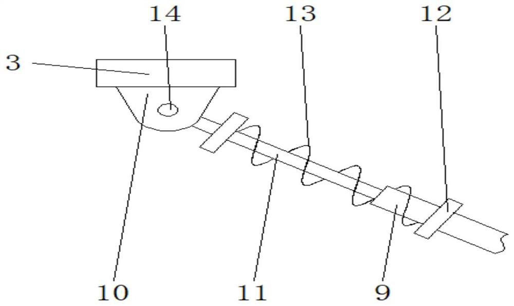
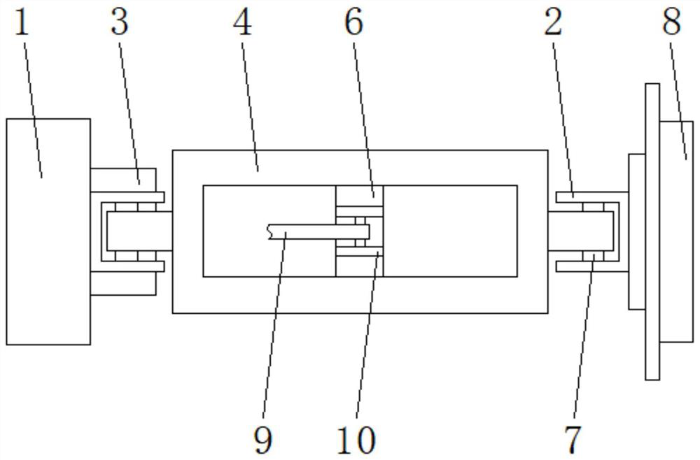
The invention discloses a single-connecting-rod type suspension structure with a stable structure. The suspension structure comprises a mounting frame, first mounting seats, a connecting rod, a firstdamping rod, a reinforcing rod, a brake disc and a second damping rod, wherein the brake disc is arranged on the outer wall of one side of the mounting frame, the first mounting seats are mounted on the outer walls of the sides, opposite to the brake disc, of the mounting frame correspondingly, the connecting rod is rotatably mounted between the first mounting seats, the reinforcing rod is weldedin the connecting rod, a limiting block is arranged on the surface of the mounting frame, second mounting seats are symmetrically mounted on the surfaces of the limiting block and the reinforcing rod,the first damping rod is arranged on the lower surface of the connecting rod, the second damping rod is arranged on the upper surface of the connecting rod, stroke rods are slidably mounted at one ends of the first damping rod and the second damping rod correspondingly, and the surfaces of the first damping rod and the second damping rod are sleeved with springs. The second damping rod and the first damping rod are arranged on the upper surface and the lower surface of the connecting rod correspondingly, the angle of the connecting rod can be elastically adjusted, and the stability of the suspension is ensured.

Description

technical field [0001] The invention relates to the technical field of automobile suspension, in particular to a structurally stable single-link suspension structure. Background technique [0002] Suspension is the general term for all force-transmitting connection devices between the frame and the axle of a car. Its function is to transmit the force and torque acting between the wheel and the frame, and to buffer the transmission from the uneven road to the frame or body. The impact force and reduce the vibration caused by it, so as to ensure that the car can run smoothly. A typical suspension structure is composed of elastic elements, guide mechanisms, shock absorbers, etc., and some structures also have buffer blocks, stabilizer bars, etc. Elastic elements are in the form of leaf springs, air springs, coil springs, and torsion bar springs. Modern car suspensions mostly use coil springs and torsion bar springs, and some high-end cars use air springs. [0003] In the exis...

Claims


Application Information

Patent Timeline
Patent Type & Authority Applications(China)
IPC IPC(8): B60G21/04B60G11/16
CPCB60G11/16B60G21/04B60G2200/40B60G2500/10
Inventor 曹甲乐
Owner 曹甲乐
Learn More