Application method of inking device of photogravure press

A gravure printing machine and ink technology, which is applied in the printing field, can solve problems such as uneven ink distribution, affecting printing quality, and the inability to effectively adjust the distance between the scraping device and the ink roller, and achieve the effect of saving costs

Active Publication Date: 2020-12-08
江苏新美亚印刷有限公司
View PDF6 Cites 0 Cited by
  • Summary
  • Abstract
  • Description
  • Claims
  • Application Information

AI Technical Summary

Problems solved by technology

[0003] The main structure of the gravure printing machine consists of five parts: paper feeding, ink feeding, printing, drying, and paper delivery. The printing part is the main process. In the printing part, the ink roller is rotated in the ink pool to supply ink and Transmission, the uniformity of the ink in the ink pool will change to varying degrees due to gravity,

Method used


Image

  • Application method of inking device of photogravure press
  • Application method of inking device of photogravure press
  • Application method of inking device of photogravure press

Examples


Embodiment 1

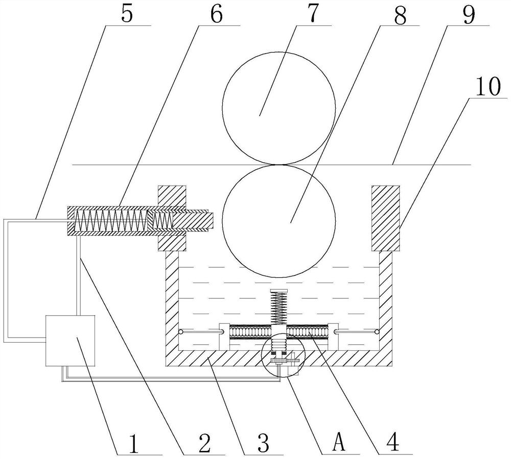
[0049] like Figure 1 to Figure 9 As shown, a method for using an inking device of a gravure printing machine of the present invention comprises the following steps:

[0050] 1) Start the motor 30, and the motor 30 drives the stirring shaft 14 to rotate in the lower tank body 3, and use the second telescopic tube to stir the ink in the lower tank body;

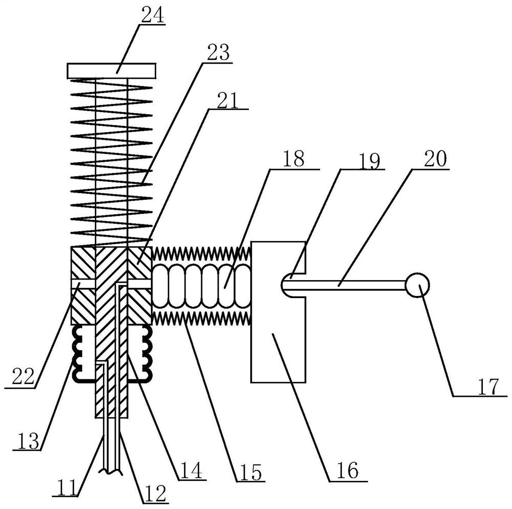
[0051] 2) Start the air pump 1 and feed high-pressure gas into the fourth air pipe 12. The high-pressure gas enters the second bellows 18 through the fourth air pipe 12, forcing the second bellows 18 to move along the inner wall of the lower pool body 11. The second bellows 18 When moving toward the inner wall of the lower tank body 3, the stirring plate 16 scrapes off the ink attached to the bottom of the lower tank body and mixes it with other inks;

[0052] 3) When the stirring plate 16 moves to fit the inner wall of the lower pool body 3, use the air pump 1 to feed high-pressure gas into the third air pipe 11, and the hig...

Embodiment 2

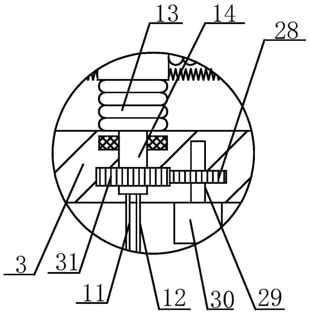
[0059] On the basis of Embodiment 1, the output end of the motor 30 extends into the lower pool body 3, the output shaft 29 of the motor 30 is provided with the first transmission gear 28, and the stirring shaft 14 is also provided with the first transmission gear. The tooth 28 meshes with the second transmission tooth 31 .

Embodiment 3

[0061] On the basis of Embodiment 1, a limit plate 24 is also provided on the top of the stirring shaft 14, a second elastic member 23 is also provided on the stirring shaft 14, and the second elastic member 23 is sleeved on the stirring shaft 14, and The second elastic member 23 is located between the limiting plate 24 and the movable block 21 .


PUM


Abstract

The invention discloses an application method of an inking device of a photogravure press. The inking device comprises an impression roller and a printing plate roller, and further comprises an air pump, a motor and an ink storage pool, the ink storage pool comprises a lower pool body and an upper pool body, and a stirring assembly is arranged at the inner bottom of the lower pool body and comprises a stirring shaft, a first telescopic pipe, multiple second telescopic pipes, a movable block and multiple stirring plates; An ink scraping assembly is arranged on one side of the upper pool body and comprises a fixed plate, a first scraping plate and multiple second scraping plates, the fixed plate horizontally penetrates into the upper pool body, a first square hole matched with the first scraping plate is further formed in the end face, located in the direction of the upper pool body, of the fixed plate, the first scraping plate is located in the first square hole, and second square holesare further formed in the first scraping plate. According to the inking device, ink stored in the ink storage pool can be stirred, the requirement for stirring the ink of different depths in an ink pool can be met, the stirring effect of the ink is improved, and meanwhile the inking amount of a printing material can be rapidly adjusted through the arranged ink scraping assembly.

Description

technical field [0001] The invention relates to the technical field of printing, in particular to a method for using an inking device of a gravure printing machine. Background technique [0002] Gravure printing is a printing method in which the inked part of the printing plate is concave. By applying ink to the concave graphic part of the printing plate, the excess ink is removed by a doctor blade or other methods, and then under the action of printing pressure, the ink is transferred to the substrate to complete the printing process. Gravure printing has clear layers, thick and bright ink layer, uniform ink color, can truly reproduce the effect of the original manuscript, and the printing speed is fast. It is one of the most widely used printing methods at present. [0003] The main structure of the gravure printing machine consists of five parts: paper feeding, ink feeding, printing, drying, and paper delivery. The printing part is the main process. In the printing part,...

Claims


Application Information

Patent Timeline
IPC IPC(8): B41F9/06B41F9/10B41F31/03B41F31/07
CPCB41F9/061B41F9/1036B41F31/03B41F31/07
Inventor 李凤英
Owner 江苏新美亚印刷有限公司
Why Eureka
Try Eureka