
Efficient pipeline dredging equipment for sewage treatment

A sewage treatment and high-efficiency technology, applied in the direction of cleaning hollow objects, cleaning methods and utensils, chemical instruments and methods, etc., can solve problems such as the ability to reduce sewage discharge, pipe bursting, waste of water resources, etc., to prevent secondary accumulation, Improve the efficiency of dredging and improve the effect of dredging

Active Publication Date: 2020-12-08
安徽泽安智成科技有限公司
View PDF22 Cites 19 Cited by
  • Summary
  • Abstract
  • Description
  • Claims
  • Application Information

AI Technical Summary

Problems solved by technology

[0006] The technical problem to be solved by the present invention is to provide a high-efficiency pipeline dredging equipment for sewage treatment. This technical solution solves most of the dredging methods by closing the pipeline, then adding high-pressure clean water at the input end of the pipeline, and flushing it open by water pressure. Impurities that are blocked in the pipeline, but this method will not only lead to a large amount of waste of water resources, but also has a certain risk of pipeline bursting. At the same time, the sewage pipe needs to be closed, which reduces the ability of sewage discharge. The existing dredging method also uses pipeline robots Desilting operation, but the existing pipeline robots can only clean in a straight line during desilting, and cannot remove the silt in the curved section of the pipeline. However, the curved section of the pipeline is the place where silt is most likely to accumulate, so the desilting effect is not good, and The existing robot desilting method is to remove the silt from the pipe wall, and the silt flows out with the water flow to achieve the dredging effect, but the dredging effect is not good when encountering large blocks of blocked silt.

Method used


Image

  • Efficient pipeline dredging equipment for sewage treatment
  • Efficient pipeline dredging equipment for sewage treatment
  • Efficient pipeline dredging equipment for sewage treatment

Examples


Embodiment Construction

[0031] In order to make the object, technical solution and advantages of the present invention clearer, the present invention will be further described in detail below in conjunction with the accompanying drawings and embodiments. It should be understood that the specific embodiments described here are only used to explain the present invention, not to limit the present invention.

[0032]In the description of the present invention, it should be noted that the terms "center", "upper", "lower", "left", "right", "front", "rear", "vertical", "horizontal", The orientation or positional relationship indicated by "inner", "outer", etc. is based on the orientation or positional relationship shown in the drawings, and is only for the convenience of describing the present invention and simplifying the description, rather than indicating or implying that the referred device or element must have Certain orientations, constructed and operative in certain orientations, therefore are not to...


PUM


Abstract

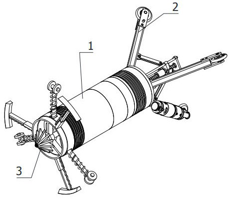
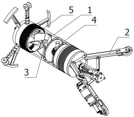
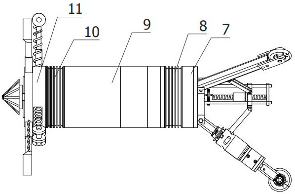
The invention relates to the technical field of pipeline sludge equipment, in particular to efficient pipeline dredging equipment for sewage treatment. The efficient pipeline dredging equipment comprises a housing, a traveling assembly, a crushing and dredging assembly, a reverse rotary mechanism and a steering drive mechanism, wherein the traveling assembly comprises a spacing regulating mechanism, a traveling drive mechanism and a front-end displacement mechanism, the spacing regulating mechanism is fixedly mounted at the tail end of the housing horizontally, and the traveling drive mechanism is fixedly mounted at the output end of the spacing regulating mechanism; the crushing and dredging assembly comprises a first crushing paddle for crushing sludge and a crushing mechanism for crushing sludge blocks, and the first crushing paddle is arranged at the front end of the housing. The efficient pipeline dredging equipment for sewage treatment disclosed by the invention can automaticallytravel in a pipeline, can quickly dredge sludge blocked in the pipeline, can flexibly turn in the pipeline, can clear sludge around the corner of the pipeline, can further perform crushing treatmenton large pieces of sludge, prevents secondary accumulation, and improves dredging effect.

Description

technical field [0001] The invention relates to the technical field of pipeline sludge equipment, in particular to a high-efficiency pipeline dredging equipment for sewage treatment. Background technique [0002] Industrial production is often accompanied by the generation of sewage, and in the sewage treatment work, the pipeline is an inevitable carrier. As the carrier of sewage treatment, the pipeline is often blocked due to the accumulation of impurities in the sewage, which will affect the sewage treatment. Seriously lead to sewage backflow or pipe bursting, resulting in environmental pollution. Therefore, in order to solve this problem, manufacturers now regularly desilt the pipeline. [0003] There are many ways to desilt existing pipelines. Most of the desilting methods are to close the pipeline, then add high-pressure clean water to the input end of the pipeline, and use water pressure to wash away the impurities blocked in the pipeline. However, this method will not...

Claims


Application Information

Patent Timeline
IPC IPC(8): B08B9/049B08B9/051
CPCB08B9/049B08B9/051B08B2209/04
Inventor 汤炬
Owner 安徽泽安智成科技有限公司
Learn More