Looped network switch cabinet

A ring network switch and switchgear technology, which is applied in substation/switch layout details, substation/switchgear cooling/ventilation, electrical components, etc., can solve the problem of low efficiency of installation and disassembly, affecting the quality of painting, and insufficient space It can save the time of installation and disassembly, avoid the separation of wires and electrical components, and facilitate inspection and maintenance.

Inactive Publication Date: 2020-12-04
浙江领方电气有限公司
View PDF4 Cites 0 Cited by
  • Summary
  • Abstract
  • Description
  • Claims
  • Application Information

AI Technical Summary

Problems solved by technology

[0003] However, during the installation process of the ring network switch cabinet, the installation position is fixed, resulting in a lot of unused space inside the ring network switch cabinet, and the space utilization rate is low. Components are disassembled from the inside of the light cabinet, resulting in low efficiency of installation and disassembly;
[0004] At the same time, when spraying paint on the surface of the ring network cabinet, the staff needs to frequently load and unload materials, resulting in low painting efficiency. At the same time, after the painting is finished, the paint is not dry, which leads to damage to the paint during the unloading process and affects the painting. quality, which in turn leads to the problem of poor painting effect

Method used


Image

  • Looped network switch cabinet
  • Looped network switch cabinet
  • Looped network switch cabinet

Examples


Embodiment 1

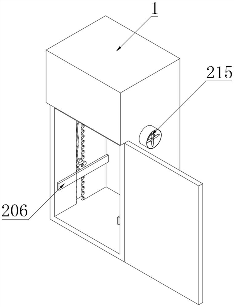
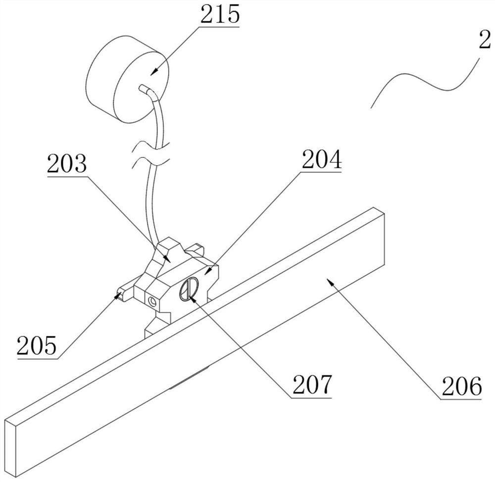
[0049] Embodiment 1: as Figure 1-7 A ring network switchgear shown includes a switchgear shell 1, and a movable installation heat dissipation assembly 2 is installed inside the switchgear enclosure 1, and the mobile installation heat dissipation assembly 2 includes a mounting groove 201, a first tooth groove 202, a moving gear 203, a fixed Tooth plate 204, anti-off plate 205, mounting plate 206, rotating column 207, movable groove 208, limit ring 209, moving spring 210, moving column 211, card slot 212, pushing plate 213, heat dissipation pipe 214, exhaust fan 215, ventilation Hole 216, driving rod 217, rotating plate 218, fixed arc plate 219 and moving hole 220;

[0050] Both ends of the switch cabinet shell 1 are provided with installation grooves 201, and one end of the installation groove 201 is provided with a first tooth groove 202, and the middle part of the first tooth groove 202 is meshed with a mobile gear 203, and one end of the mobile gear 203 is movably installed...


PUM


Abstract

A looped network switch cabinet disclosed by the present invention comprises a switch cabinet shell, the two ends in the switch cabinet shell are both equipped with the installation grooves, one end of each installation groove is equipped with a first tooth groove, and the middle part in each first tooth groove is engaged with a mobile gear. One end of each mobile gear is movably equipped with a fixed toothed plate, and the other end of each mobile gear is movably equipped with an anti-drop plate. An installation plate is welded to one end of the fixed toothed plate, a limiting ring is installed at one end in the movable groove through a screw, and a movable spring is welded to one end of the limiting ring. One end of the movable spring is welded to one end of a movable column, and a clamping groove is formed in the position, corresponding to the movable column, of the first toothed groove.Compared with the prior art, according to the looped network switch cabinet, the electric appliance elements can be quickly assembled and disassembled, the mounting and dismounting time is saved, workers do not need to dismount a large number of screws, the labor intensity of the workers is reduced, the mounting positions of the electrical components can be quickly changed, the space is fully utilized, and the space utilization rate is increased.

Description

technical field [0001] The invention relates to the technical field of ring network switch cabinets, in particular to a ring network switch cabinet. Background technique [0002] The ring network cabinet is a set of high-voltage switchgear installed in a steel plate metal shell or made into an assembled spaced ring network power supply unit. Its core part uses load switches and fuses. It has simple structure, small size, low price, and It has the advantages of improving power supply parameters and performance and power supply security. It is widely used in distribution stations and box-type substations of load centers such as urban residential quarters, high-rise buildings, large public buildings, factories and enterprises. During the preparation process of the ring main unit, It is necessary to spray paint on the surface of the ring network cabinet to protect the surface of the ring network cabinet. [0003] However, during the installation process of the ring network swit...

Claims


Application Information

Patent Timeline
Patent Type & Authority Applications(China)
IPC IPC(8): H02B1/32H02B1/56H02B1/20
CPCH02B1/20H02B1/32H02B1/565
Inventor 陈建
Owner 浙江领方电气有限公司
Why Eureka
Try Eureka