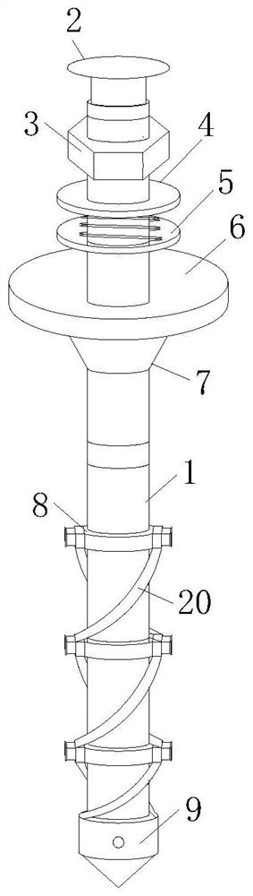
Flexible anchor rod

A bolt and flexible technology, which is applied in the installation of bolts, sheet pile walls, excavation, etc., can solve the problems of easy loosening, insufficient friction, and unstable anchor bolts, etc., and achieve good and stable fixing effects

Inactive Publication Date: 2020-12-04
侯小柱
View PDF0 Cites 0 Cited by
  • Summary
  • Abstract
  • Description
  • Claims
  • Application Information

AI Technical Summary

Problems solved by technology

[0002] Anchor is the most basic part of roadway support in contemporary coal mines. It reinforces the surrounding rock of the roadway so that the surrounding rock can support itself. Now the bolt is not only used in mines, but also in engineering technology. Slopes, tunnels, and dams are mainly reinforced. The anchor rod is used as a tension member that penetrates into the ground. One end of it is connected to the engineering structure, and the other end is deep into the ground. The whole anchor rod is divided into a free section and an anchoring section. The free section refers to It transmits the tension at the head of the anchor to the area of ​​the anchor, and its function is to apply prestress to the anchor; the traditional anchor has some disadvantages. First, the circular gasket is not firm when fixing the anchor, and it is easy to use for a long time It is loose and troublesome to use. Secondly, when the anchor is fixed in the formation, there are no multiple fixing devices, and the friction generated by the fixing is not enough, so the ideal fixing effect cannot be achieved. In order to solve the above problems, we propose this flexible anchor

Method used


Image

  • Flexible anchor rod
  • Flexible anchor rod
  • Flexible anchor rod

Examples


Embodiment approach

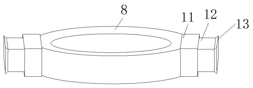
[0027] As an embodiment of the present invention, the anchor body 1 is provided with a hollow cavity; the connection disc 8 is provided with a connection hole 16; the connection hole 16 is used to communicate with the cavity and the casing 11 inside; a group of sliding plates 15 are slidably installed in the cavity; two sliding plates 15 are provided, and the two sliding plates 15 are fixedly connected by fixed rods, wherein the sliding plate 15 above is provided with a The magnet is in contact with a push rod 18; the end of the push rod 18 is provided with a No. 2 magnet 17 magnetically attracted to the No. 1 magnet, and the push rod 18 can move downward instantly under the push of an external force, thereby pushing two sliding plates 15 moves downward synchronously, the sliding plate 15 compresses the gas below, and the gas is sprayed out through the connecting hole 16 after being pressurized, so that the telescopic block 12 in the sleeve pipe 11 flies out instantly. When wo...


PUM


Abstract

The invention relates to the field of anchor rods, and particularly relates to a flexible anchor rod. The flexible anchor rod comprises an anchor rod body, wherein a slurry blocking plug is arranged at the upper end of the anchor rod body; a rotating nut is arranged below the slurry blocking plug on the outer side of the anchor rod body; a first soft gasket is arranged at the lower end of the rotating nut on the outer side of the anchor rod body; a first spring is arranged at the lower end of the first soft gasket on the outer side of the anchor rod body; a second soft gasket is arranged at the lower end of the first spring on the outer side of the anchor rod body; a connecting disc is arranged below the second soft gasket on the outer side of the anchor rod body; a sleeve is arranged at one end of the connecting disc; and a second spring is arranged in the sleeve. According to the flexible anchor rod, the anchor rod body can be fixed more stably through a round base plate, the anchorrod body can be fixed more firmly in the stratum, the service life is longer, the anchor rod is safer, and the flexible anchor rod can bring better use prospects.

Description

technical field [0001] The invention relates to the field of anchor rods, in particular to a flexible anchor rod. Background technique [0002] Anchor is the most basic part of roadway support in contemporary coal mines. It reinforces the surrounding rock of the roadway so that the surrounding rock can support itself. Now the bolt is not only used in mines, but also in engineering technology. Slopes, tunnels, and dams are mainly reinforced. The anchor rod is used as a tension member that penetrates into the ground. One end of it is connected to the engineering structure, and the other end is deep into the ground. The whole anchor rod is divided into a free section and an anchoring section. The free section refers to It transmits the tension at the head of the anchor to the area of ​​the anchor, and its function is to apply prestress to the anchor; the traditional anchor has some disadvantages. First, the circular gasket is not firm when fixing the anchor, and it is easy to u...

Claims


Application Information

Patent Timeline
Patent Type & Authority Applications(China)
IPC IPC(8): E21D21/00E02D5/74E02D17/20
CPCE02D5/74E02D17/20E21D21/0026E21D21/008
Inventor 侯小柱陈启
Owner 侯小柱
Why Eureka
Try Eureka