
Electromagnet response tester

A technology for electromagnets and testers, applied in the directions of instruments, measuring electricity, measuring devices, etc., can solve the problems of short time, small response time difference of electromagnets, difficult detection, etc., and achieve easy and understandable operation, simple structure, and test results. Precise and unmistakable results

Inactive Publication Date: 2020-12-01
安阳凯地磁力科技股份有限公司
View PDF7 Cites 5 Cited by
  • Summary
  • Abstract
  • Description
  • Claims
  • Application Information

AI Technical Summary

Problems solved by technology

[0004] Since the response time of the electromagnet is an instantaneous process, the time is very short, and the difference in the response time of the electromagnets with different performances is smaller, which is not easy to detect

Method used


Image

  • Electromagnet response tester
  • Electromagnet response tester
  • Electromagnet response tester

Examples


Embodiment Construction

[0035] The technical solutions of the present invention will be clearly and completely described below in conjunction with the embodiments. Obviously, the described embodiments are part of the embodiments of the present invention, but not all of them. Based on the embodiments of the present invention, all other embodiments obtained by persons of ordinary skill in the art without making creative efforts belong to the protection scope of the present invention.

[0036] In describing the present invention, it is to be understood that the terms "center", "longitudinal", "transverse", "length", "width", "thickness", "upper", "lower", "front", " Back", "Left", "Right", "Straight", "Horizontal", "Top", "Bottom", "Inner", "Outer", "Clockwise", "Counterclockwise", etc. or The positional relationship is based on the orientation or positional relationship shown in the drawings, which is only for the convenience of describing the present invention and simplifying the description, rather t...


PUM


Abstract

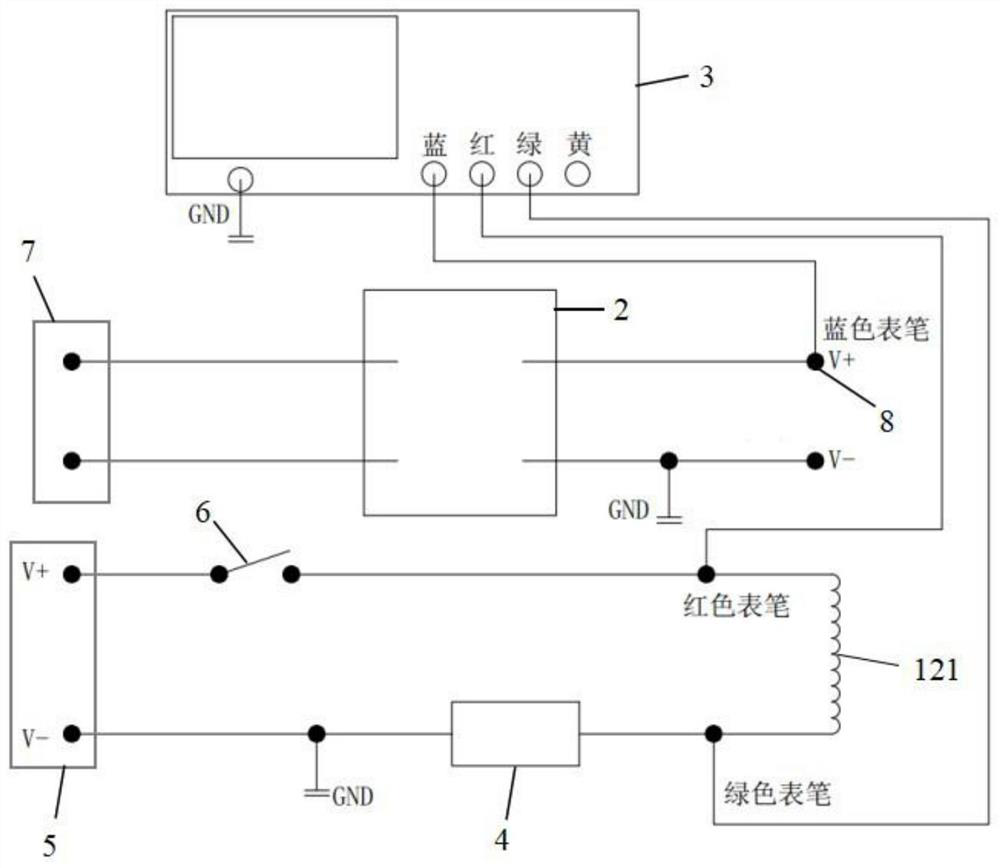
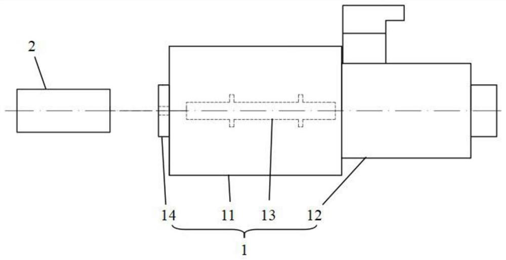
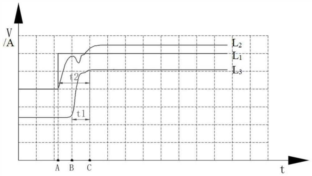
The invention provides an electromagnet response tester which comprises a hydraulic electromagnetic valve, an oscilloscope and a laser displacement sensor, a through hole is formed in an end cover ofthe valve body of the hydraulic electromagnetic valve, and laser emitted by the laser displacement sensor can be emitted into the valve body through the through hole and used for sensing the positionof a valve element of the hydraulic electromagnetic valve; the laser displacement sensor is electrically connected with the oscilloscope and used for collecting output voltage capable of reflecting the displacement of the valve element. Two ends of a coil of the electromagnet are connected with an electromagnet power supply, a time relay is connected in series between the coil and the electromagnet power supply, and on-off of the electromagnet is controlled through the time relay; the two ends of the coil of the electromagnet are connected with the oscilloscope in parallel and used for collecting the voltage at the two ends of the coil of the electromagnet and the current passing through the electromagnet. According to the invention, the voltage and current of the coil and the displacementcurve of the valve element are displayed on the oscilloscope, and the accurate on-off response time of the electromagnet can be obtained by analyzing the curve, so that the performance of the electromagnet is judged.

Description

technical field [0001] The invention relates to the technical field of electromagnet performance testing, in particular to an electromagnet response tester. Background technique [0002] With the continuous development of science and technology, hydraulic technology is widely used in various fields such as industry, agriculture, and medical treatment, which also means that there are increasingly strict technical requirements for the quality and performance of each component of the hydraulic system. [0003] As an essential power component in the hydraulic system, the electromagnet's performance directly determines the operating conditions of the hydraulic system. Therefore, the performance requirements of the electromagnet are getting higher and higher, and the response time of the electromagnet is an important indicator of the performance of the electromagnet, and its requirements are becoming more and more stringent. [0004] Since the response time of the electromagnet i...

Claims


Application Information

Patent Timeline
Patent Type & Authority Applications(China)
IPC IPC(8): G01R31/00
CPCG01R31/00
Inventor 孟凡朋岳玉霞黄猛
Owner 安阳凯地磁力科技股份有限公司
Learn More