
Draught fan of extractor hood and extractor hood

A range hood, fan technology, applied in the direction of removing oil fume, machines/engines, mechanical equipment, etc., can solve the problems of difficult exhaust air, poor oil fume suction effect, etc., and achieve the effect of enhancing suction

Pending Publication Date: 2020-12-01
VATTI CORP LTD
View PDF0 Cites 1 Cited by
  • Summary
  • Abstract
  • Description
  • Claims
  • Application Information

AI Technical Summary

Problems solved by technology

[0004] In order to overcome the deficiencies in the above-mentioned prior art, the main purpose of the present invention is to provide a range hood fan and a range hood, which can solve the problem that the range hood in the kitchen is difficult to exhaust air and has poor smoke absorption effect.

Method used


Image

  • Draught fan of extractor hood and extractor hood
  • Draught fan of extractor hood and extractor hood
  • Draught fan of extractor hood and extractor hood

Examples


Embodiment 1

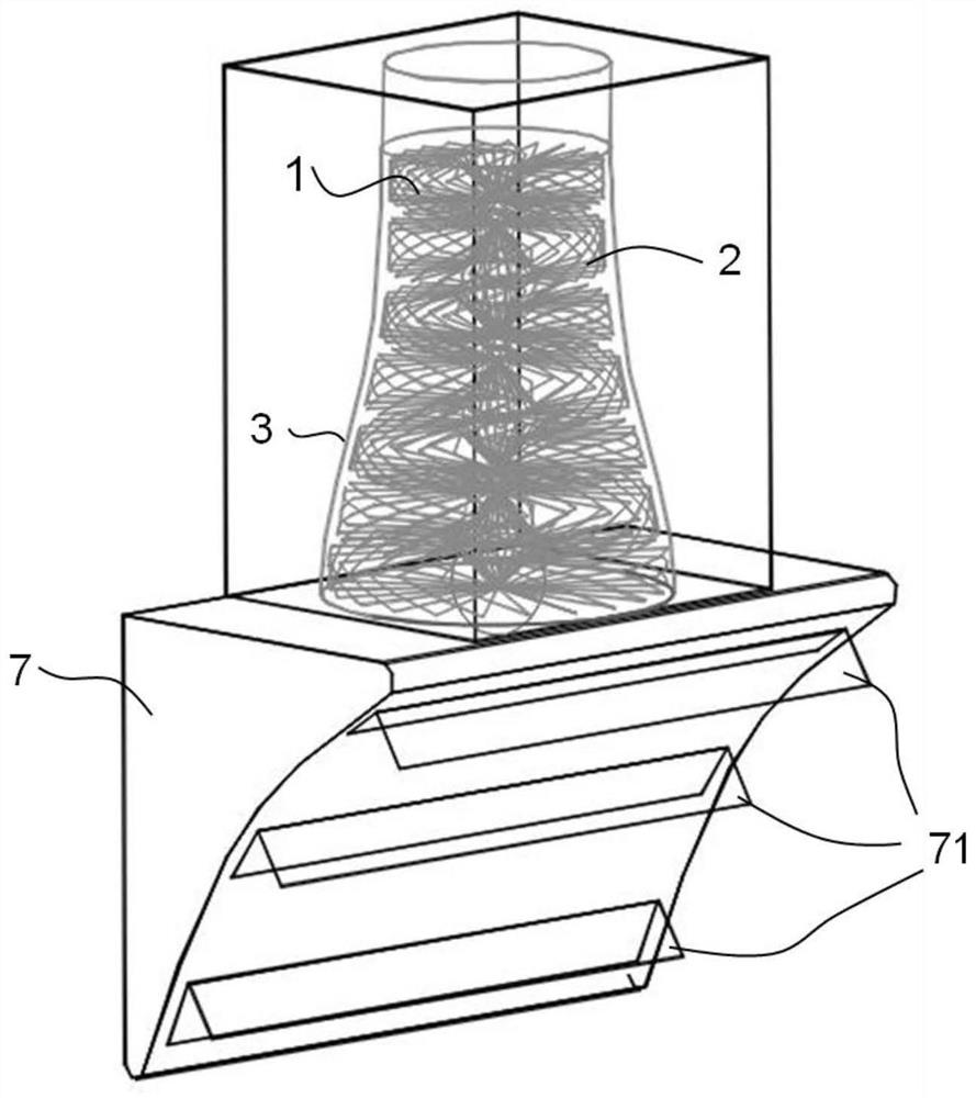
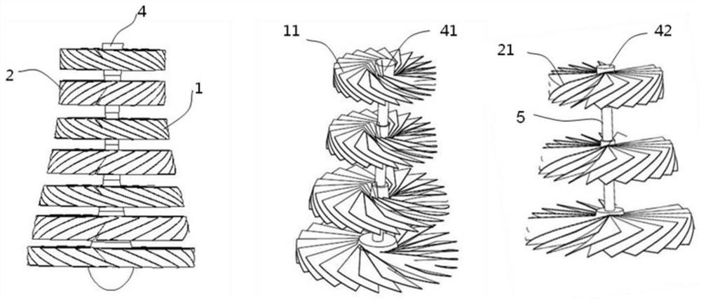
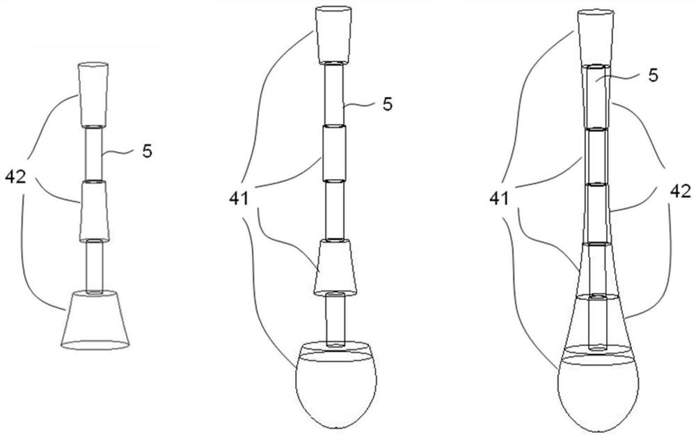
[0024] Embodiment 1 of the present invention provides a fan for a range hood, such as figure 1 and 2 As shown, it includes the impeller assembly and the fan volute 3, the impeller assembly includes the forward impeller 1 and the reverse impeller 2, the forward impeller 1 is composed of a plurality of forward rotating impeller blades 11, and the reverse impeller 2 is composed of a plurality of reverse rotating impeller blades 21. The forward impeller 1 and the reverse impeller 2 are coaxially arranged at intervals and rotate in opposite directions.

[0025] In this way, when the fan is working, the forward impeller 1 and the reverse impeller 2 rotate at the same time, so that the airflow pressure is recursively pushed inside the fan volute 3, and the internal static pressure of the fan can be quickly increased layer by layer within the shortest distance, and the oil fume is continuously generated. The strong suction greatly enhances the oil fume suction effect.

[0026] The f...

Embodiment 2

[0035] Embodiment 2 of the present invention provides a range hood, which includes a smoke collection hood 7 and a fan of the range hood provided in Embodiment 1. The smoke collection hood 7 is provided with three air intake holes 71, and the range hood The blower fan is installed on the fume collecting hood 7 tops.

[0036] The air intake hole 71 comprises an upper air intake hole, a middle air intake hole and a lower air intake hole, the lower air intake hole has the largest width, the middle air intake hole width is next, and the upper air intake hole has the smallest width. The lower air intake hole has the largest width and large air intake volume, which can ensure that the rising oil fume can be sucked in as soon as the airflow starts to rise, reducing the diffusion of oil fume; the upper air intake hole has a small width and large negative pressure, which can ensure that the rising oil fume is diffused The fume is sucked in. By setting different air intake widths, it i...


PUM


Abstract

The invention discloses a draught fan of an extractor hood. The draught fan comprises a draught fan volute and an impeller assembly arranged in the draught fan volute, the impeller assembly comprisesa forward impeller composed of a plurality of forward rotating impeller blades and a reverse impeller composed of a plurality of reverse rotating impeller blades, and the forward impeller and the reverse impeller are coaxially arranged at an interval and are opposite in rotating direction. Meanwhile, the invention further provides the extractor hood using the draught fan, the extractor hood further comprises an exhaust fume collecting hood, and the exhaust fume collecting hood is provided with three air inlets with different widths. According to the draught fan, the forward impeller and the reverse impeller rotate at the same time, the internal static pressure of the draught fan is increased layer by layer within the shortest distance, the pressurizing effect is better than that of one-wayrotary pressurizing, meanwhile, the draught fan volute which is gradually closed up in the direction from the air inlets to an air outlet is adopted in a matched manner, the internal static pressureof the extractor hood is gradually increased, and continuous high-strength suction force is generated for lampblack.

Description

technical field [0001] The invention belongs to the technical field of range hoods, and in particular relates to a fan of the range hood and the range hood. Background technique [0002] Range hoods have become one of the indispensable kitchen appliances in modern families. Air volume, wind pressure and noise are the core indicators of range hoods. When the range hood is in use, 85% of the users feel that the suction of the range hood is small and the suction is not clean. Users generally believe that the maximum suction and the effect of the range hood are their biggest needs when purchasing a range hood. In recent years, the entire industry has collectively entered the era of high suction power. High suction hoods have also become the first choice for consumers to buy range hoods. The market share has risen far faster than other types of hoods, and it has truly been generally recognized by consumers. [0003] As the core component of the range hood, the rationality of the...

Claims


Application Information

Patent Timeline
Patent Type & Authority Applications(China)
IPC IPC(8): F04D29/28F04D29/30F04D29/44F24C15/20
CPCF04D29/281F04D29/30F04D29/441F24C15/20
Inventor 韩君庆潘叶江
Owner VATTI CORP LTD
Learn More