
Throttle valve key opening degree flow detection equipment

A flow detection and throttle valve technology, which is applied in the direction of internal combustion engine testing, etc., can solve the problems of inaccurate exhaust temperature control, large or small flow consistency deviation in the middle opening, and increased air volume control time. quality effect

Pending Publication Date: 2020-11-27
WUXI LONGSHENG TECH
View PDF0 Cites 0 Cited by
  • Summary
  • Abstract
  • Description
  • Claims
  • Application Information

AI Technical Summary

Problems solved by technology

[0004] The opening MAP of the throttle valve is calibrated based on the standard throttle valve sample in the early stage of engine development. If the flow consistency of the throttle valve is too large in the mass production in the later stage, the deviation from the standard parts will cause the throttle valve to be adjusted repeatedly, resulting in Increased air volume control time and inaccurate exhaust temperature control occurred
Moreover, during the production process of the throttle valve, the sensors are only programmed at the fully open and fully closed positions, and the sensor voltage at the middle opening is directly linearized according to the values ​​of fully open and fully closed. This programming method is more convenient and fast, but There will inevitably be a certain deviation when the throttle valve is fully open and fully closed. This deviation between different throttle valves may cause large or small flow consistency deviations in the middle opening; at the same time, different throttles There is also a certain deviation in the leakage of the fully closed position between the valves, so the flow deviation in the middle opening of the throttle valve cannot be truly fed back simply by testing the angle difference of the throttle valve plate.

Method used


Image

  • Throttle valve key opening degree flow detection equipment

Examples


Embodiment Construction

[0016] The present invention will be further described in detail below in conjunction with the accompanying drawings and specific embodiments.

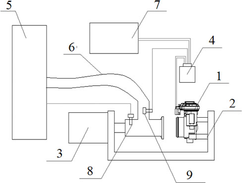
[0017] A throttle key opening flow detection device, its structure is as follows figure 1 As shown, it includes a U-shaped tooling 2, a controller 7, a vehicle computer board 4, and an air supply testing mechanism. The U-shaped tooling 2 is fixed on the work surface, and four passing bolts are arranged on the right inner wall of the U-shaped tooling 2. Install the pin of the throttle, the throttle 1 to be tested is installed in the pin of the inner wall on the right side of the U-shaped tooling 2, and the air supply testing mechanism is arranged on the left side wall of the U-shaped tooling 2.

[0018] The air supply test mechanism is used to compress the throttle valve when detecting the throttle valve, supply air to the throttle valve and perform the test, and when replacing the throttle valve, it is separated from the throttle valv...


PUM


Abstract

The invention discloses throttle valve key opening degree flow detection equipment. The equipment comprises a U-shaped tool fixedly arranged on a working table. A throttle valve to be tested is installed on the inner wall of the right side of the U-shaped tool. An air supply testing mechanism for pressing the throttle valve and supplying air to the throttle valve is arranged on the inner wall of the left side of the U-shaped tool, the air supply testing mechanism is connected with a vehicle computer board, and the vehicle computer board adjusts the opening degree of the throttle valve througha controller and judges the flow consistency of the key opening degree of the throttle valve. The equipment is simple in structure, and can conveniently detect a single throttle valve, so as to judgewhether the flow consistency of the key position of the throttle valve deviates from a standard value or not; and in the detection process, the working condition of the throttle valve on the engine can be accurately simulated, the valve plate angle of the throttle valve is truly reflected, and the quality of outgoing products is guaranteed.

Description

technical field [0001] The invention relates to the technical field of throttle valve production, in particular to a device for detecting the flow consistency of throttle valve opening. Background technique [0002] The throttle valve is installed between the intake manifold and the intercooler of the car, and is used to throttle the fresh air on the diesel engine, so that the combustion speed of diesel in the engine cylinder will be slowed down. The throttle valve is used to increase the exhaust temperature of the engine during the running of the car so that the after-treatment of the car can quickly reach the optimal working temperature. The calculated signal is used to control the opening of the throttle valve, thereby adjusting the air flow, and further controlling the combustion speed in the engine cylinder by controlling the amount of air participating in the combustion. When the air volume decreases, the combustion speed slows down. Part of the combustion takes place...

Claims


Application Information

Patent Timeline
Patent Type & Authority Applications(China)
IPC IPC(8): G01M15/05
CPCG01M15/05
Inventor 于政
Owner WUXI LONGSHENG TECH
Learn More