
A cable ditch drainage structure and drainage method for embankment-road integration project

A drainage structure and cable trench technology, which is applied to drainage structures, waterway systems, water supply devices, etc., can solve the problems of water flow energy dissipation and deceleration, low cost, and difficulty in inspection and maintenance, so as to reduce the impact of erosion, low cost, and easy inspection and maintenance. The effect of maintenance

Active Publication Date: 2022-05-13
CHANGJIANG SURVEY PLANNING DESIGN & RES
View PDF11 Cites 0 Cited by
  • Summary
  • Abstract
  • Description
  • Claims
  • Application Information

AI Technical Summary

Problems solved by technology

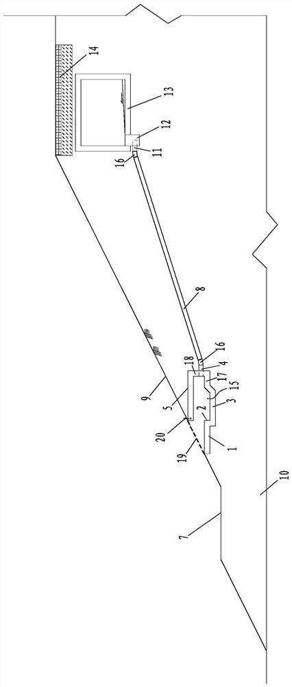
[0008] The first purpose of the present invention is to provide a cable ditch drainage structure for the embankment-road integration project, which can achieve the purpose of energy dissipation and buffering with a relatively low cost and a small structure, and achieve a good landscape effect through structural treatment, which is convenient for inspection and maintenance; solve the problem of anti-scour of embankment slope, the problem of energy dissipation and deceleration of water flow, and the problem of difficult inspection and maintenance

Method used


Image

  • A cable ditch drainage structure and drainage method for embankment-road integration project
  • A cable ditch drainage structure and drainage method for embankment-road integration project
  • A cable ditch drainage structure and drainage method for embankment-road integration project

Examples


Embodiment

[0089] The present invention will now be described in detail by taking the application of the present invention to embankment slope drainage of cable trenches in a new embankment and road integration project as an example, and it also has a guiding effect on the application of the present invention to embankment slope drainage of cable trenches in other embankment projects.

[0090] The brief introduction of a new embankment and road integration project is as follows:

[0091] A newly built embankment and road integration project, the flood control standard is once in 50 years, the embankment grade is 3, the slope ratio of the side of the embankment is 1:3, and a first-level embankment is set. The embankment crest is the main road of the city, the embankment crest is 22m wide, two-way 4 lanes are set, the total width of the motor vehicle lane is 16m, sidewalks are on both sides, and the single width is 3m. The cable trench is arranged under the sidewalk on the backwater side, a...


PUM


Abstract

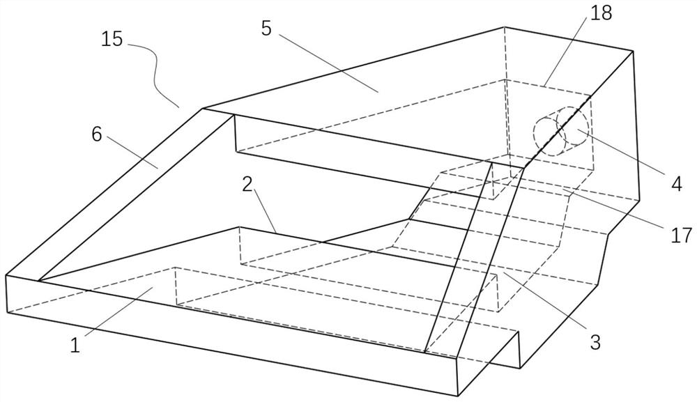
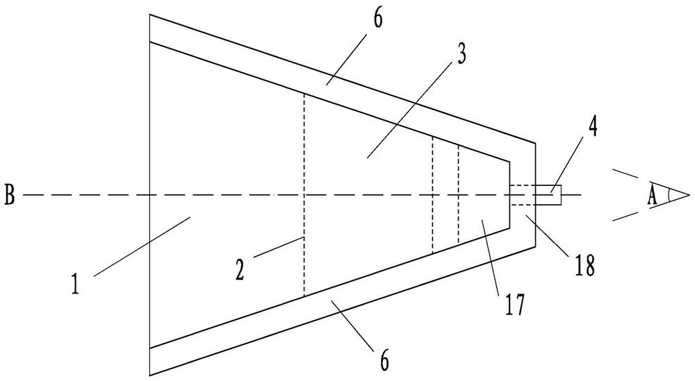
The invention discloses a cable ditch drainage structure for an embankment-road integration project. It includes energy dissipation drainage culvert inlet pipe, drainage connection pipe, cable trench outlet pipe and energy dissipation drainage culvert; the drainage connection pipe is located below the side of the cable trench outlet pipe and above the side of the energy dissipation drainage culvert inlet pipe; one end of the drainage connection pipe is connected to the The outlet pipe of the cable trench is connected, and one end is connected with the inlet pipe of the energy dissipation drainage culvert; the inlet pipe of the energy dissipation drainage culvert is anchored on the side wall of the energy dissipation drainage culvert; the energy dissipation drainage culvert is located above the embankment platform and buried in the embankment slope ; The height between the energy dissipation drainage culvert and the dike platform is less than or equal to 0.5m; the energy dissipation drainage culvert is a hollow structure with one end open; the seepage well is connected to the lower end of the cable trench; the cable trench outlet pipe is connected to the lower end of the seepage well side. The invention has the advantages of achieving the purpose of energy dissipation and buffering of cable ditch drainage with a relatively low cost and a small structure, and can achieve good landscape effects. The invention also discloses a drainage method for the cable ditch drainage structure of the embankment-road integration project.

Description

technical field [0001] The invention relates to the technical field of drainage of embankments and roads, and more specifically relates to a drainage structure for cable trenches of embankments and roads. The invention also relates to a drainage method for the cable ditch drainage structure of the embankment-road integration project. Background technique [0002] With the rapid development of the city, the ecological green development and the construction of the urban basic road network are constantly integrated. The embankment and road integration project is one of the products of the development of green ecological cities. In recent years, it has gradually become a new focus of engineering construction. The waterfront construction of the embankment project, under the basic premise of meeting the flood control requirements, creates an excellent urban waterfront landscape space, and at the same time integrates the road on the top of the embankment with the main road network ...

Claims


Application Information

Patent Timeline
Patent Type & Authority Patents(China)
IPC IPC(8): E03F5/00E03F3/02E03F3/04
CPCE03F5/00E03F3/02E03F3/04
Inventor 黄永何子杰刘国强沈晓明
Owner CHANGJIANG SURVEY PLANNING DESIGN & RES
Learn More