A magnetic stirring device and stirring and mixing equipment
A technology of magnetic stirring device and stirring shaft, which is applied to mixers, mixer accessories, transportation and packaging, etc., can solve the problem of no long-distance transmission of power, and achieve long-term stable and reliable operation, high production efficiency, and high precision. Effect
- Summary
- Abstract
- Description
- Claims
- Application Information
AI Technical Summary
Problems solved by technology
Method used
Image
Examples
Embodiment 1
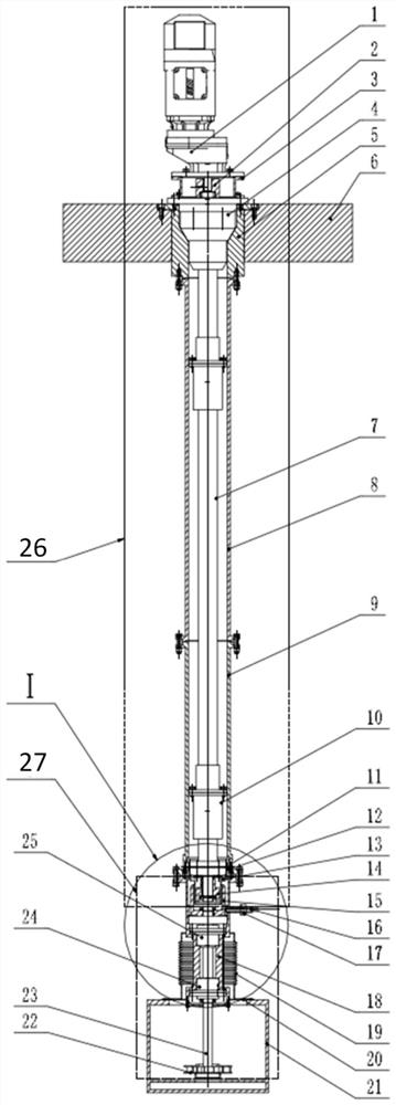
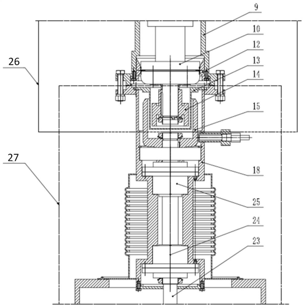
[0047] This embodiment discloses a magnetic stirring device, such as figure 1As shown, it includes an upper stirring shaft assembly 26, a lower stirring shaft assembly 27 and a magnetic coupling, the upper stirring shaft assembly 26 includes an upper stirring shaft, the lower stirring shaft assembly 27 includes a lower stirring shaft 23, and the upper stirring shaft and the lower stirring shaft 23 Connection via magnetic coupling. In the magnetic stirring device in this embodiment, the stirring shaft is designed in sections by setting the upper stirring shaft assembly and the lower stirring shaft assembly, so that the long-distance power transmission of the magnetic stirring device can be realized, and it is stable and reliable, avoiding the need for an integral stirring shaft. During the stirring process, the stirring shaft is easily broken due to excessive force on the stirring shaft.
[0048] In this embodiment, the magnetic coupling adopts a cylindrical permanent magnet d...
Embodiment 2
[0061] This embodiment discloses a stirring and mixing equipment, which includes a mixing and clarifying tank 21, which is arranged in a heat chamber, and also includes the magnetic stirring device in Embodiment 1, and the upper stirring shaft assembly of the magnetic stirring device is fixedly arranged on the shielding On the cover plate 6, it is used to stir and mix the liquid in the clarification tank 21.
[0062] In this embodiment, the upper stirring shaft assembly further includes a supporting sleeve, wherein the upper end of the supporting sleeve is connected to the shielding cover plate 6 . Optionally, a shielding plug 5 is also provided between the upper end of the supporting sleeve and the shielding cover plate 6, the shielding plug 5 has an inner hole, and the inner hole wall of the shielding plug 5 is a tapered surface, which is used to connect the upper end of the supporting sleeve It is clamped in the inner hole of the shielding plug 5 to realize the axial positi...
PUM
 Abstract
Description
Claims
Application Information
 - Generate Ideas
- Intellectual Property
- Life Sciences
- Materials
- Tech Scout
- Unparalleled Data Quality
- Higher Quality Content
- 60% Fewer Hallucinations
Browse by: Latest US Patents, China's latest patents, Technical Efficacy Thesaurus, Application Domain, Technology Topic, Popular Technical Reports.
© 2025 PatSnap. All rights reserved.Legal|Privacy policy|Modern Slavery Act Transparency Statement|Sitemap|About US| Contact US: help@patsnap.com


