Packaging support structure and light-emitting device comprising packaging support structure

一种封装支架、发光装置的技术,应用在发光领域,能够解决LED光亮未能达到预期、影响LED发光效率等问题,达到减少上件误差、不易断裂或变形的效果

Inactive Publication Date: 2020-11-24
EVERLIGHT ELECTRONICS
View PDF11 Cites 0 Cited by
  • Summary
  • Abstract
  • Description
  • Claims
  • Application Information

AI Technical Summary

Problems solved by technology

[0004] On the other hand, the heat energy generated by LED operation often affects the luminous efficiency of LEDs, making the brightness of LEDs fail to meet expectations

Method used


Image

  • Packaging support structure and light-emitting device comprising packaging support structure
  • Packaging support structure and light-emitting device comprising packaging support structure
  • Packaging support structure and light-emitting device comprising packaging support structure

Examples


Embodiment 2

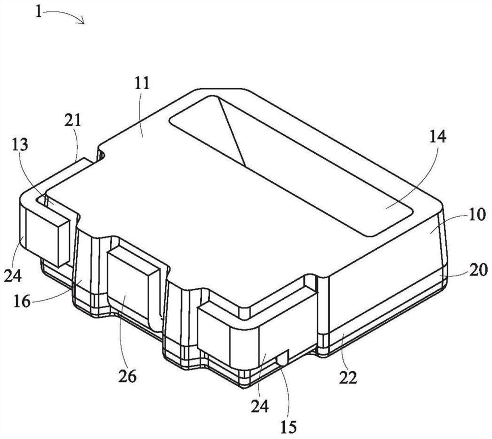
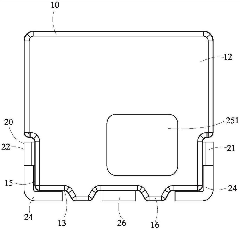
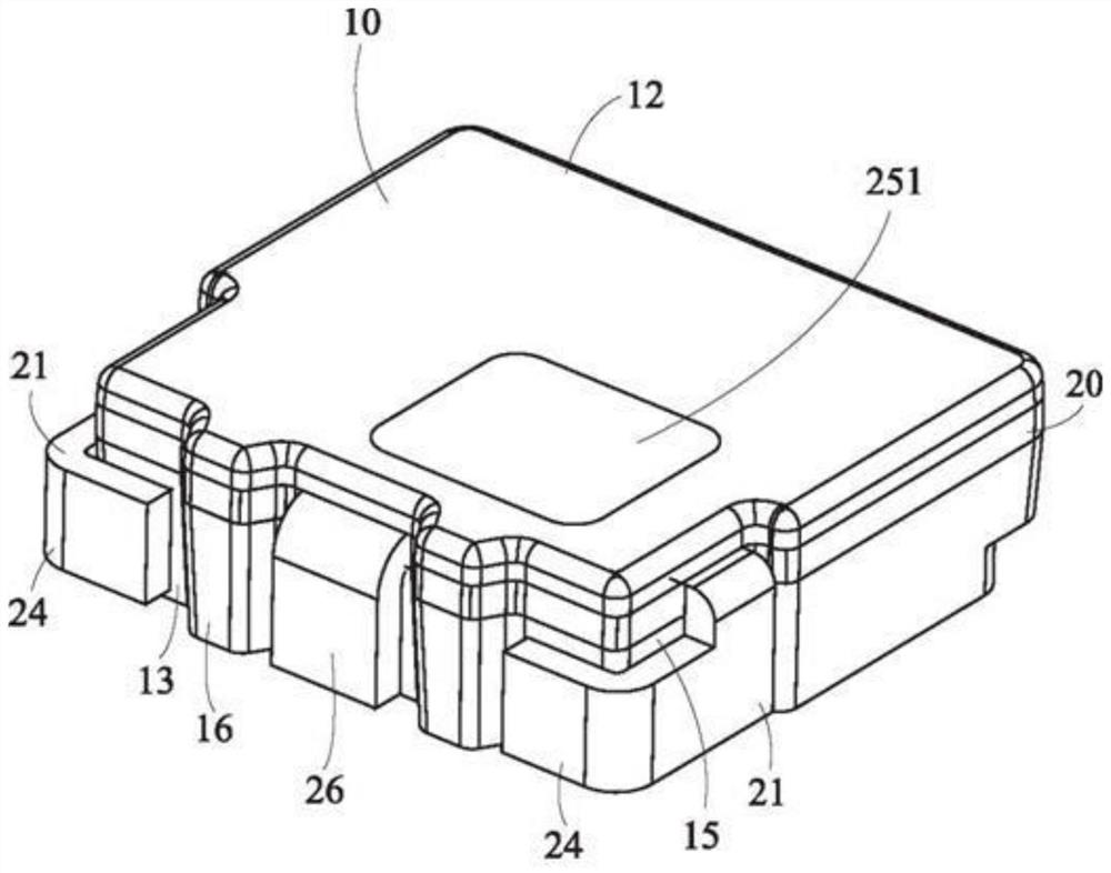
[0066] Figure 5 is a schematic structural view of the light-emitting device provided in Embodiment 2 of the present invention, Figure 6A-6B It is a structural schematic diagram when the substrate has a supporting mechanism in the light-emitting device provided by Embodiment 2 of the present invention, Figure 7A It is a schematic structural view of the quantum dot material and the phosphor material in the encapsulating colloid in the light-emitting device provided by Embodiment 2 of the present invention after being inverted and centrifuged, Figure 7B It is a schematic diagram of the structure when the quantum dot material and phosphor material in the encapsulation colloid are uniformly distributed, Figure 7C It is a schematic diagram of the structure when the quantum dot material and phosphor material are distributed in layers in the encapsulation colloid.

[0067] The above-mentioned embodiment is an explanation of the technical content of the packaging support structu...


PUM

PropertyMeasurementUnit
wavelengthaaaaaaaaaa
particle diameteraaaaaaaaaa

Abstract

The invention provides a packaging support structure and a light-emitting device comprising a packaging support structure. The packaging support structure comprises a shell, wherein the shell comprises a light emitting surface, a backlight surface, a bottom surface and a groove; and a conductive support, which is partially wrapped by the shell and comprises a first pin and a second pin which are separated from each other, wherein the first pin and the second pin each comprise an electrode part and a bending part, and the electrode parts are exposed out of the shell through the groove, and thebending part and the electrode parts extend outwards to the outside of the shell and are bent towards the bottom surface of the shell. One of the first pin and the second pin further comprises a heatdissipation part, and the heat dissipation part extends outwards from the electrode part and is exposed out of the backlight surface of the shell. The packaging support structure provided by the embodiment achieves the effects of reducing loading errors and effectively eliminating heat energy.

Description

technical field [0001] The present invention relates to the field of lighting, in particular to a package bracket structure and a light emitting device including the package bracket mechanism. Background technique [0002] More and more displays equipped with current electronic products use light-emitting diodes (LEDs) as light-emitting elements, and the light emitted by the LEDs can be evenly emitted from the panel of the display through components such as light guide plates. More specifically, the LED is first arranged in a packaging structure, and then the packaging structure is arranged on a substrate, and the light incident surface of the light guide plate is aligned with the LED, so that the light emitted by the LED enters into the guide as much as possible. Light parts to reduce the occurrence of light leakage. Therefore, if the alignment between the LED and the light guide is inaccurate, it will cause light leakage, which will lead to problems such as poor display e...

Claims


Application Information

Patent Timeline
Patent Type & Authority Applications(China)
IPC IPC(8): H01L33/62H01L33/48H01L33/64
CPCH01L33/48H01L33/62H01L33/647G02B6/009G02B6/4269H01L33/486H01L33/642G02B6/0073H01L33/507H01L33/508H01L33/644
Inventor 刘建男陈登暐康桀侑杨皓宇李昱达
Owner EVERLIGHT ELECTRONICS
Why Eureka
Try Eureka