Eureka AIR delivers breakthrough ideas for toughest innovation challenges, trusted by R&D personnel around the world.

Glucose sensor and measurement correction method

A technology of a glucose sensor and a calibration method, which is applied in the field of blood glucose measuring devices, can solve the problems of few models, increase the difficulty of the production process, and increase the research and development of test strips and production costs, and achieves cost saving, good test accuracy, and reduced effect of influence

Active Publication Date: 2020-11-24
JIANGSU YUYUE MEDICAL EQUIP&SUPPLY CO LTD +1
View PDF9 Cites 12 Cited by
  • Summary
  • Abstract
  • Description
  • Claims
  • Application Information

AI Technical Summary

Problems solved by technology

The advantage of this scheme is that the measured HCT has high accuracy and has a wide range. Generally, 10-70% or even 0-70% can be tested accurately, but the disadvantage is that it is necessary to increase the AC test impedance module and The supporting electrode structure greatly increases the cost of test paper development and production, and greatly increases the difficulty of the production process
This solution is often used in some high-end models, limited by cost, there are few corresponding models on the market

Method used


Image

  • Glucose sensor and measurement correction method
  • Glucose sensor and measurement correction method
  • Glucose sensor and measurement correction method

Examples


no. 1 Embodiment

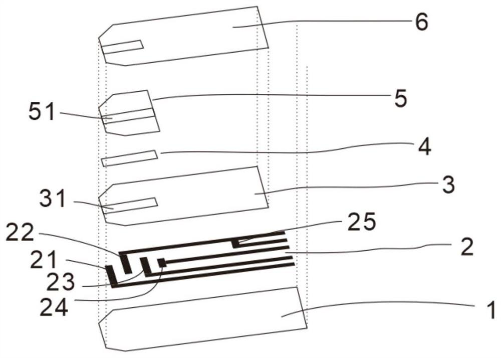
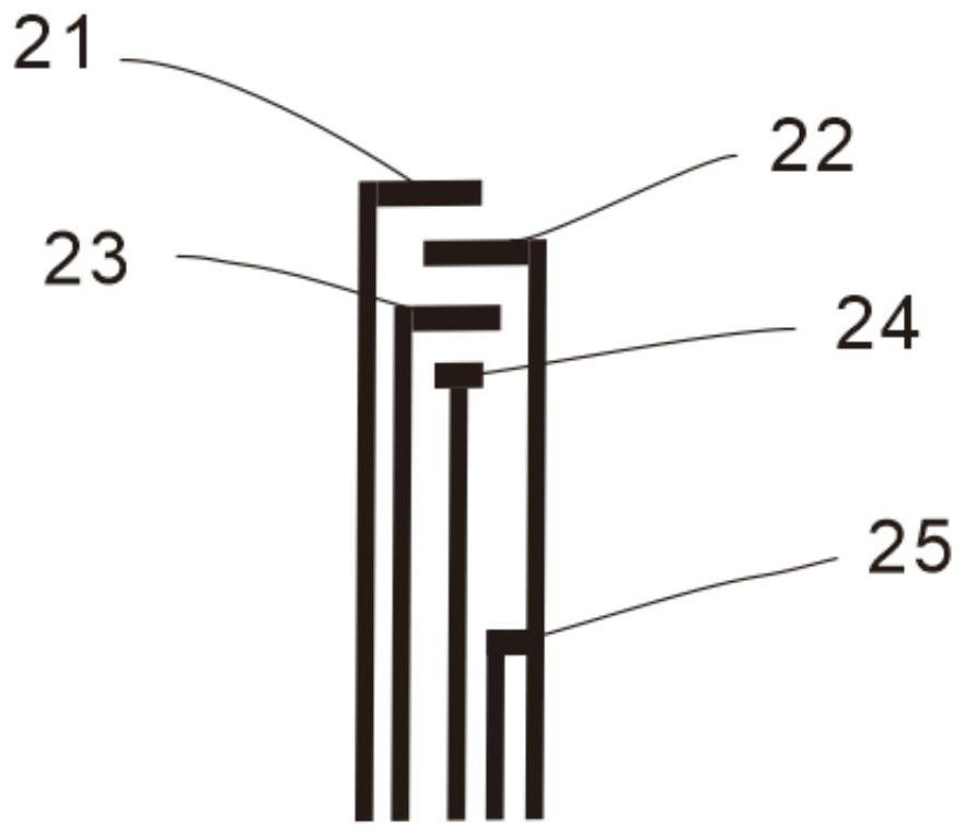
[0024] The first specific embodiment: the glucose sensor structure includes: substrate layer 1, electrode layer 2, insulating layer 3, reagent layer 4, hydrophilic spacer combination layer 5 and masking tape layer 6, see figure 1 . Wherein the electrode layer 2 is printed onto the substrate layer 1 by screen printing, and the electrode layer 2 is provided with a first time detection electrode 21, a counter electrode 22, a working electrode 23, a sampling detection electrode 24, a power button 25, and electrodes and electrodes. For wires connected to the instrument, see figure 2 . The insulating layer 3 covers the electrode layer 2 , and blank windows 31 are left on the detecting electrode 21 , the counter electrode 22 , the working electrode 23 and the sampling detection electrode 24 at the first time. The reagent layer 4 covers the blank window provided on the insulating layer 3 and is cured on the surface of the electrode layer 2 by heating. The hydrophilic spacer combin...

no. 2 Embodiment

[0036] Second specific embodiment: Glucose sensor On the basis of the first specific embodiment of the glucose sensor, the electrode layer 2 is optimized and adjusted, and the second time detection electrode 26 is added. See Figure 4 , increasing the distance between the two time recording points, greatly increasing the gradient of the entire time difference Δt, making the fitting of the hematocrit ratio more accurate and the accuracy of the final reading value higher. When the blood flows to the first time detection electrode 21 and the second time detection electrode 26, record the time point t 1 , when the blood flows to the sampling detection electrode 24, record the time point t 2 .

[0037] The above glucose sensor tested 6 blood samples with different hematocrit ratios at room temperature, recorded the sampling time Δt respectively, repeated the test 10 times for each blood sample, and took the average value. The test results are shown in Table 2. Then the average va...


PUM


Abstract

The invention discloses a glucose sensor. The glucose sensor comprises a substrate layer and an electrode layer, wherein the electrode layer is arranged on the substrate layer, and a first time detection electrode, a working electrode, a counter electrode and a sample injection detection electrode are arranged on the electrode layer; and the counter electrode is arranged between the working electrode and the sample injection detection electrode. The invention also discloses a glucose measuring method. The invention also discloses a glucose measurement correction method. The hematocrit ratio ofa blood sample is converted according to the time when a whole sample injection channel is filled with blood and a measured current and the time difference delta t between two recorded times, then the glucose current value is corrected and compensated through the hematocrit ratio and the environment temperature measured by the temperature sensor, and finally the glucose value is converted and displayed. The cost of instruments and test paper is greatly saved; and the method has better test accuracy in a wider erythrocyte hematocrit ratio range.

Description

technical field [0001] The invention belongs to a blood glucose measuring device, in particular to a glucose sensor and a measuring and correcting method. Background technique [0002] Currently on the market, there are two commonly used technical solutions for the influence of the hematocrit ratio (hereinafter referred to as HCT) on the test results: 1) Relying on the adjustment and optimization of the formula itself, adjusting and optimizing the hemolytic agent and the electronic medium in the formula Type and dosage, to minimize the impact of HCT on test results. The advantage of this solution is that the cost is low, but the disadvantage is that a large number of different hemolytic agents and electronic mediators need to be tried, the research and development costs are high, and the effect is often poor. The application range of HCT is small, generally ranging from 30-55% or even smaller; [0003] 2) Add an alternating current test impedance module through the test pa...

Claims


Application Information

Patent Timeline
Patent Type & Authority Applications(China)
IPC IPC(8): G01N27/26
CPCG01N27/26
Inventor 马召栋郭栋赵梁陈建军
Owner JIANGSU YUYUE MEDICAL EQUIP&SUPPLY CO LTD
Why Eureka
Eureka Blog
Learn More