Rotary waterproof button lock

A rotary and push-button technology, which is applied in the field of aircraft flap locks, can solve problems that cannot meet the requirements of military products, large operating space and opening size, and weak load-bearing capacity, and achieve fast, reliable, and good unlocking and locking operations. Aerodynamic shape, the effect of improving safety

Pending Publication Date: 2020-11-24
东方蓝天钛金科技有限公司
View PDF0 Cites 2 Cited by
  • Summary
  • Abstract
  • Description
  • Claims
  • Application Information

AI Technical Summary

Problems solved by technology

The rotary quick release lock is easy to use and small in size, but its load bearing capacity is relatively weak; the snap button quick release lock can withstand large loads, but the operating space and opening size are large; the hook tongue quick release lock has good sealing performance And larger load-bearing capacity, but only suitable for larger wall thickness
[0004] At present, the connecting locks used in aerospace operation covers have the disadvantages of large size, heavy weight, unchanged operation, openings for both the hole cover and the opening frame, and the inability to seal against rain, and it is extremely inconvenient to lock and open. Meet the requirements of increasingly high-speed military products

Method used


Image

  • Rotary waterproof button lock
  • Rotary waterproof button lock
  • Rotary waterproof button lock

Examples


Embodiment Construction

[0052] The principles and features of the present invention are described below in conjunction with examples, which are only used to explain the present invention and are not intended to limit the scope of the present invention.

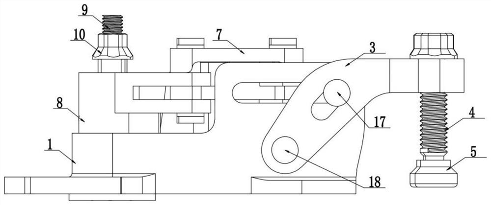
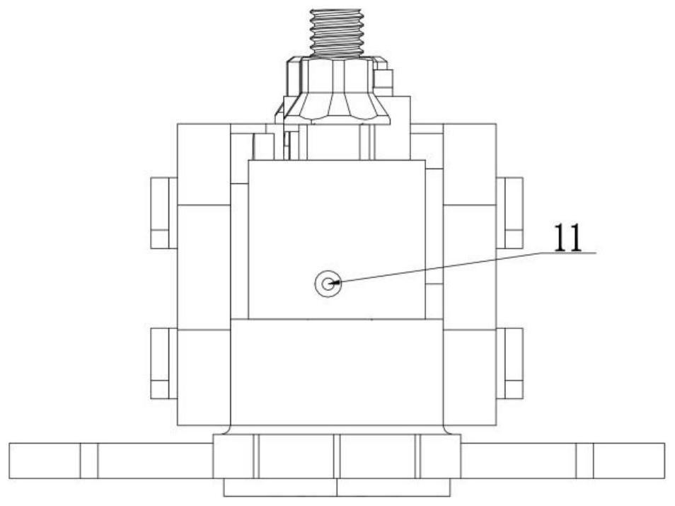
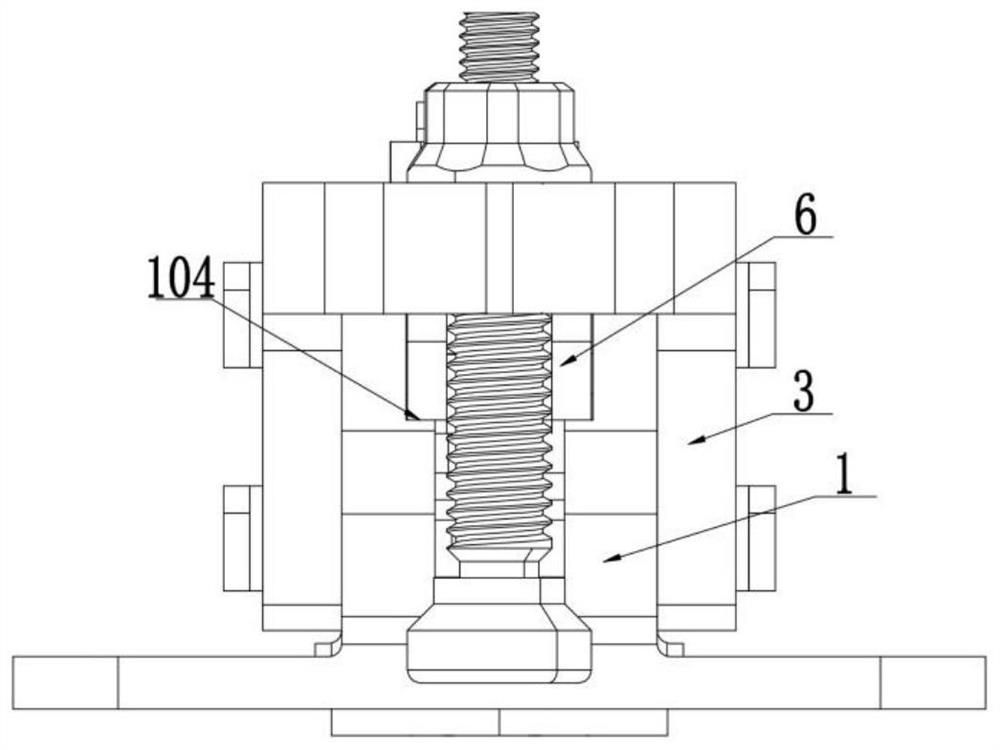
[0053] Such as Figure 1-Figure 23 As shown, a rotary waterproof button lock includes a lock base 1, a drive assembly, a swing arm 8, a slider 6, a support 3 and a pressure head. One side of the lock base 1 is provided with a drive jack 101, and the other side There is a chute 102 on it, the drive assembly includes a shaft housing 2 and a push rod 9 inserted in the shaft housing, the shaft housing is sleeved in the drive socket, and the shaft housing 2 is provided with A through groove 201, the push rod 9 is provided with a pin shaft 15, the pin shaft extends into the through groove, a spring 12 is provided on the push rod below the pin shaft, and a spring 12 is provided on the lock seat. A locking groove 103 adapted to the end of the pin;

[0054]...


PUM


Abstract

The invention discloses a rotary waterproof button lock. The rotary waterproof button lock comprises a lock seat, a driving assembly, a swing arm, a sliding block, a support and a pressing head, wherein the driving assembly comprises a shaft shell and an ejector rod; the shaft shell is sleeved with a driving insertion hole; a through groove is formed in the shaft shell; a pin shaft is arranged onthe ejector rod and extends into the through groove; a spring is arranged in the portion, below the pin shaft, of the ejector rod; a locking groove matched with the end of the pin shaft is formed in the lock seat; the sliding block is installed in a sliding groove; the swing arm is connected with the shaft shell and hinged to the sliding block through a connecting rod; the support is bent; one endof the support is hinged to the lock seat, a guide groove is formed in the middle of the support, and the other end of the support is connected with the pressing head; a shifting pin is arranged on the sliding block and extends into the guide groove; and a sliding supporting face used for guiding the sliding block is arranged in the lock seat. The rotary waterproof button lock is simple in structure, small in size, low in weight and convenient to install, unlocking and locking operation is rapid and reliable, no protruding structure exists on the surface of an opening cover after installation, and the good aerodynamic configuration of an airplane is guaranteed.

Description

technical field [0001] The invention relates to a rotary waterproof button lock, which belongs to the technical field of aircraft flap locks. Background technique [0002] In order to ensure that the airborne equipment on the aircraft is maintained and repaired in a timely manner, the surface of the aircraft needs to be provided with a large number of covers. The covers are divided into quick-release covers and non-quick-release covers according to their characteristics. The lid generally only needs to be simply pressed, twisted, or the entire flap can be opened or closed with a simple tool. [0003] At present, the fast opening and closing of various types of flaps used on aircraft can be mainly divided into several types such as rotary type, screw type, snap button type, hook tongue type, and integral detachable type in terms of mechanism principle and operation mode. Rotary quick-release locks are easy to use and small in size, but relatively weak in load bearing capacit...

Claims


Application Information

Patent Timeline
IPC IPC(8): E05B65/00E05B17/00E05C19/00B64C1/14
CPCB64C1/1446E05B17/002E05B65/006E05C19/00E05Y2900/502E05Y2900/538
Inventor 王晓亮崔云先王肇宇牛光景王善岭刘超峰王冠华刘珂潘永秋吕亮徐建超
Owner 东方蓝天钛金科技有限公司
Why Eureka
Try Eureka