A two-way slotting device for wooden boards used in hand workshops
A workshop and wood board technology, which is applied in the field of two-way grooving devices for wood boards used in hand workshops, can solve the problems of inability to guarantee the position of the grooving, slow and uniform grooving speed, etc. Effect
- Summary
- Abstract
- Description
- Claims
- Application Information
AI Technical Summary
Problems solved by technology
Method used
Image
Examples
Embodiment 1
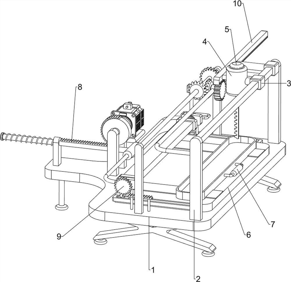
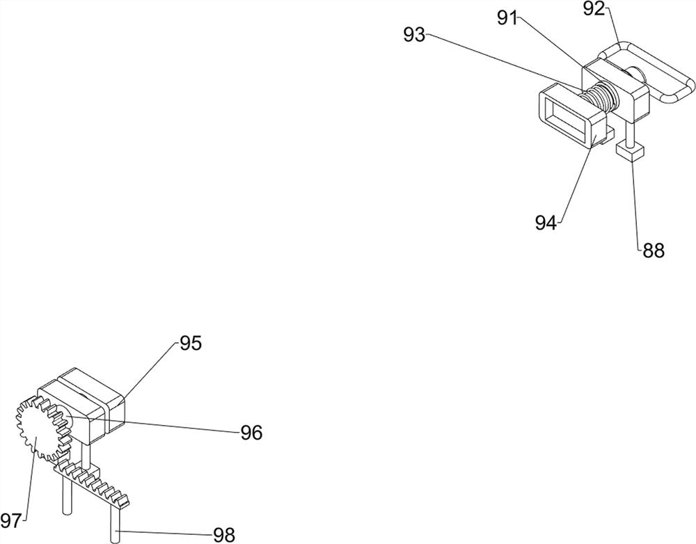
[0023] A two-way slotting device for wooden boards used in hand workshops, such as figure 1 , figure 2 , image 3 , Figure 4 As shown, it includes a base 1, a sliding rod frame 2, a first sliding sleeve 3, a mounting frame 4, an electric saw 5, a sliding rail block 6, a material receiving frame 7, a reciprocating mechanism 8 and a rotating mechanism 9. On the right side of the base 1 A sliding rod frame 2 is provided, a first sliding sleeve 3 is slidably arranged on the sliding rod frame 2, an installation frame 4 is arranged on the left side of the first sliding sleeve 3, a chainsaw 5 is installed on the installation frame 4, and a middle set on the base 1 is provided. There is a sliding rail block 6 , a receiving frame 7 is slidably arranged on the sliding rail block 6 , a reciprocating mechanism 8 is arranged on the left side of the base 1 , and a rotating mechanism 9 is arranged in the middle of the base 1 .
[0024] First, people place the wooden board to be slotted ...
Embodiment 2
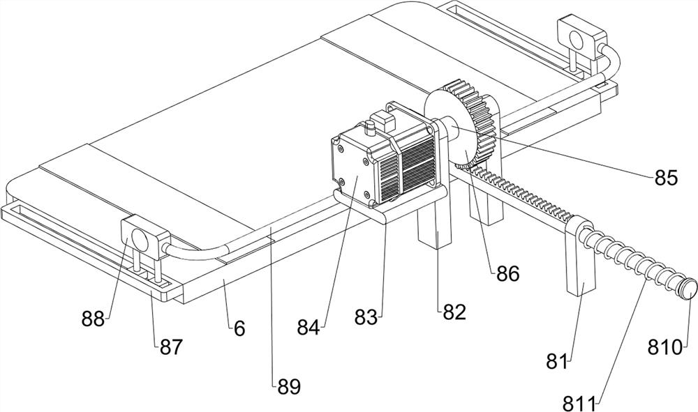
[0026] On the basis of Example 1, as figure 1 , figure 2 , image 3 , Figure 4 As shown, the reciprocating mechanism 8 includes a sliding sleeve rod 81, a support frame 82, a mounting plate 83, a motor 84, a first rotating shaft 85, a half gear 86, a sliding rail 87, a sliding block 88, a connecting rod 89, and a rack rod 810. and the first compression spring 811, the slide rail block 6 is provided with slide rail bars 87 on the front and rear sides, the slide rail bars 87 are slidably provided with slide blocks 88, and a connecting rod 89 is provided between the two slide blocks 88, and the base A support frame 82 is provided on the left side of the upper part 1, a mounting plate 83 is provided on the rear side of the support frame 82, a motor 84 is mounted on the mounting plate 83, and a first rotating shaft 85 is provided on the output shaft of the motor 84, and the first rotating shaft 85 passes through the support The first rotating shaft 85 is provided with a half g...
Embodiment 3
[0031] On the basis of Example 2, as figure 1 and Figure 5 As shown, a moving mechanism 10 is also included. The base 1 is provided with a moving mechanism 10 in the middle. The moving mechanism 10 includes a second rack 101, a bracket 102, a rotating column 103, a second gear 104, a bevel gear set 105, and a U-shaped The rod 106 , the third gear 107 , the third rack 108 and the second sliding sleeve 109 , a bracket 102 is symmetrically arranged in the middle of the base 1 , and a rotating column 103 is rotatably arranged between the two brackets 102 . A second gear 104 is provided on the side through the one-way clutch, a second rack 101 is provided on the sliding block 88 on the rear side, the second gear 104 is meshed with the second rack 101, and the sliding rod frame 2 is slidably provided with a second rack 101. The sliding sleeve 109, the left side of the second sliding sleeve 109 is provided with a third rack 108, the front part of the third rack 108 is connected wit...
PUM
 Abstract
Description
Claims
Application Information
 - Generate Ideas
- Intellectual Property
- Life Sciences
- Materials
- Tech Scout
- Unparalleled Data Quality
- Higher Quality Content
- 60% Fewer Hallucinations
Browse by: Latest US Patents, China's latest patents, Technical Efficacy Thesaurus, Application Domain, Technology Topic, Popular Technical Reports.
© 2025 PatSnap. All rights reserved.Legal|Privacy policy|Modern Slavery Act Transparency Statement|Sitemap|About US| Contact US: help@patsnap.com


