
Electrical control box

A technology of electrical control boxes and servo motors, which is applied in the direction of electrical components, electrical equipment structural parts, electrical equipment shells/cabinets/drawers, etc., can solve the problems of not being able to achieve energy conservation and environmental protection, small maintenance space, and splashing, etc. Achieve the effects of energy saving and environmental protection in the way of heat dissipation, increase the maintenance space, and facilitate maintenance operations

Inactive Publication Date: 2020-11-20
YANGZHOU YONGRUI MACHINERY CO LTD
View PDF6 Cites 4 Cited by
  • Summary
  • Abstract
  • Description
  • Claims
  • Application Information

AI Technical Summary

Problems solved by technology

[0002] At present, the electrical control box is assembled in a closed or semi-closed metal cabinet or on a screen width with switchgear, measuring instruments, protective appliances and auxiliary equipment according to the requirements of electrical wiring. A large number of electrical control boxes will be needed in construction. The building electrical control box is easily splashed by rainwater, cement slurry and other debris into the interior of the building electrical control box. Rainwater and cement slurry usually enter the inside of the electrical box through the cooling holes, which is likely to cause accidents
[0003] The electrical control box in the prior art is only equipped with an inspection door, which leads to the problems of small inspection space and low operation and inspection efficiency during the inspection process; and in actual operation, the cooling fan of the heat dissipation mechanism is always in the running state, and the energy consumption is high. Can not achieve the effect of energy saving and environmental protection

Method used


Image

  • Electrical control box
  • Electrical control box
  • Electrical control box

Examples


Embodiment Construction

[0027] In order to make the technical means, creative features, goals and effects achieved by the present invention easy to understand, the present invention will be further described below in conjunction with specific embodiments.

[0028] In describing the present invention, it should be understood that the terms "upper", "lower", "front", "rear", "left", "right", "top", "bottom", "inner", " The orientation or positional relationship indicated by "outside", etc. is based on the orientation or positional relationship shown in the drawings, and is only for the convenience of describing the present invention and simplifying the description, rather than indicating or implying that the referred device or element must have a specific orientation, so as to Specific orientation configuration and operation, therefore can not be construed as limiting the present invention; in the description of the present invention, it should be noted that, unless otherwise clearly specified and limit...


PUM


Abstract

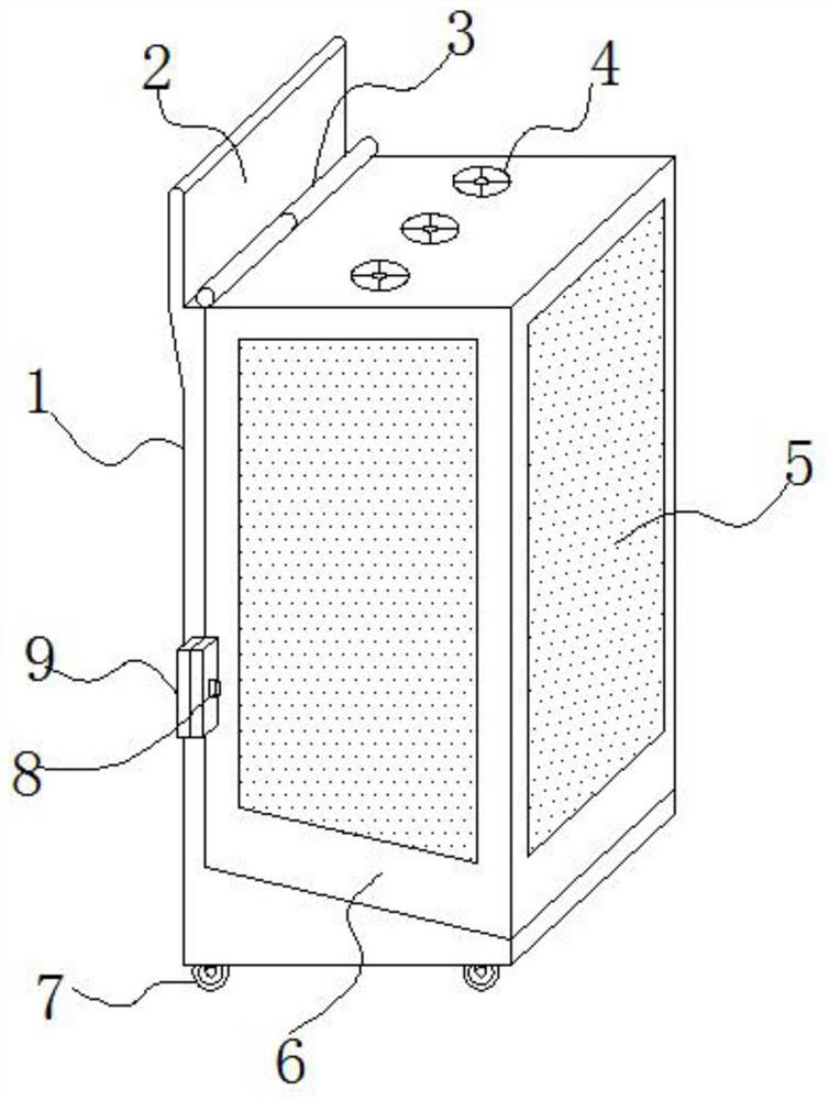
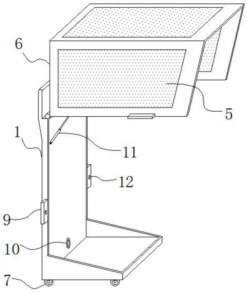
The invention relates to the technical field of electrical control and discloses an electrical control box. The electrical control box comprises a base, universal wheels are fixedly installed at the four corners of the bottom of the base respectively, a side plate is fixedly installed on the upper portion of the base, the upper portion of the base is movably hinged to the left side of the upper portion of a protective cover through a pin shaft, and a round pipe vertically and fixedly penetrates through the middle of the upper portion of the protective cover. The protective cover is rotated andopened through the pin shaft, the protective cover can reach a horizontal stable state under the supporting effect of the hydraulic supporting rod, on one hand, the top of the head of an operator canbe protected through the opened protective cover through the combination mode, falling objects are prevented from injuring the operator, and the safety is improved; and after the protective cover isrotated and opened, the rectangular mounting box on the whole base can be exposed, so that the overhauling space can be increased, the overhauling operation of an operator is more convenient, and theoperation is very convenient.

Description

technical field [0001] The invention relates to the technical field of electrical control, in particular to an electrical control box. Background technique [0002] At present, the electrical control box is assembled in a closed or semi-closed metal cabinet or on a screen width with switchgear, measuring instruments, protective appliances and auxiliary equipment according to the requirements of electrical wiring. A large number of electrical control boxes will be needed in construction. The building electrical control box is easily splashed by rainwater, cement slurry and other sundries into the interior of the building electrical control box. Rainwater and cement slurry usually enter the inside of the electrical box through the cooling holes, which is easy to cause accidents. [0003] The electrical control box in the prior art is only equipped with an inspection door, which leads to the problems of small inspection space and low operation and inspection efficiency during t...

Claims


Application Information

Patent Timeline
Patent Type & Authority Applications(China)
IPC IPC(8): H05K5/02H05K7/20
CPCH05K5/0217H05K5/0234H05K7/20209H05K7/20136H05K5/03
Inventor 吴俊权
Owner YANGZHOU YONGRUI MACHINERY CO LTD
Learn More