
Multi-power-supply complementary power supply device and control method thereof

A power supply device and multi-power supply technology, applied in circuit devices, emergency power supply arrangements, photovoltaic power generation, etc., can solve the problems of low power supply efficiency, high solution cost, short-term power supply interruption, etc., to achieve high power supply efficiency and ensure seamless switching. Effect

Inactive Publication Date: 2020-11-20
博阳能源科技有限公司
View PDF8 Cites 1 Cited by
  • Summary
  • Abstract
  • Description
  • Claims
  • Application Information

AI Technical Summary

Problems solved by technology

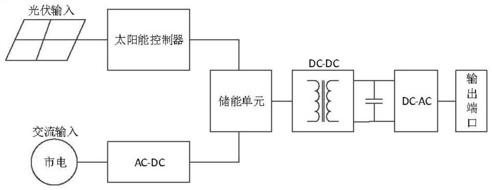
[0005] The above two methods have the following problems. First, the utility power directly charges the energy storage unit through AC-DC. Although the seamless switching between photovoltaic and utility power can be realized, the AC-DC needs to be isolated, and there are multi-level circuits afterwards. The cost of the solution is high, and the overall power supply efficiency is very low; second, the photovoltaic and mains are switched by switches. Although the efficiency is high, there is a short power supply interruption at the moment of switching, and the risk is high. For some important applications, it is not allowed to happen. Temporary power interruption, otherwise huge losses will be caused

Method used


Image

  • Multi-power-supply complementary power supply device and control method thereof
  • Multi-power-supply complementary power supply device and control method thereof
  • Multi-power-supply complementary power supply device and control method thereof

Examples


Embodiment Construction

[0041]In order to make the purposes, technical solutions and advantages of the embodiments of the present application clearer, the technical solutions in the embodiments of the present application will be clearly and completely described below in conjunction with the drawings in the embodiments of the present application. Obviously, the described embodiments It is a part of the embodiments of this application, not all of them. Based on the embodiments in this application, all other embodiments obtained by persons of ordinary skill in the art without creative efforts fall within the protection scope of this application.

[0042] On the basis of the existing two methods, the present invention proposes a new topology structure and control method, which not only ensures seamless switching, no short-term interruption of power supply, but also ensures higher power supply efficiency.

[0043] Now in conjunction with accompanying drawing and specific embodiment describe technical sche...


PUM


Abstract

The invention provides a multi-power-supply complementary power supply device and a control method thereof. The multi-power-supply complementary power supply device comprises a photovoltaic power supply branch, a mains supply input branch, an inverter and a system controller; the photovoltaic power supply branch comprises a solar controller, an energy storage unit and a photovoltaic voltage adjusting circuit which are sequentially arranged from photovoltaic input; the mains supply input branch comprises a mains supply conversion circuit connected with the mains supply; the output end of the photovoltaic voltage adjusting circuit and the output end of a first voltage boosting / reducing DC-DC unit are connected in parallel to a DC bus of the inverter; a first acquisition circuit is arranged between the system controller and the photovoltaic power supply branch; a second acquisition circuit is arranged between the system controller and the mains supply input branch; and the control outputend of the system controller is connected with the mains supply conversion circuit and the photovoltaic voltage adjusting circuit. Compared with the prior art, seamless switching between photovoltaicand mains supply is realized, short-time interruption of load power supply is avoided, and huge economic loss is avoided.

Description

technical field [0001] The invention belongs to the technical field of electric power generation systems, and in particular relates to a multi-power supply complementary power supply device and a control method thereof. Background technique [0002] In the application of off-grid photovoltaic power generation system, due to the instability of photovoltaic power supply, it needs to be used as a complement to the mains power supply. The two power sources need to be switched and controlled. There are mainly two existing methods: [0003] The first such as figure 1 Shown: The mains is connected to the energy storage unit through AC-DC. When it is judged that the photovoltaic energy does not meet the load demand, the photovoltaic charging is turned off, the mains path is opened, and the mains charges the energy storage unit. After DC-DC, DC- After AC conversion, power is supplied to the load. [0004] The second such as figure 2 Shown: The AC power output by photovoltaic powe...

Claims


Application Information

Patent Timeline
IPC IPC(8): H02J9/08H02J9/06
CPCH02J9/062H02J9/08H02J9/068Y02B10/70Y02E10/56
Inventor 杨峰任翔涛康博纬
Owner 博阳能源科技有限公司
Learn More