
Hose joint, hose pipeline and method for producing hose joint

A technology for hose joints and hoses, applied in the directions of pipes/pipe joints/pipes, hose connection devices, hoses, etc., can solve the problems of increased hose pipeline structure and manufacturing cost, and avoid unfavorable reductions. , The effect of accurate installation and simple installation

Pending Publication Date: 2020-11-20
NEOPERL
View PDF10 Cites 0 Cited by
  • Summary
  • Abstract
  • Description
  • Claims
  • Application Information

AI Technical Summary

Problems solved by technology

If such a hose line is configured as a two-chamber or multi-chamber hose line (the two-chamber or multi-chamber hose line has two or more chambers), then the construction and manufacturing costs of such a hose line will additionally increase

Method used


Image

  • Hose joint, hose pipeline and method for producing hose joint
  • Hose joint, hose pipeline and method for producing hose joint
  • Hose joint, hose pipeline and method for producing hose joint

Examples


Embodiment Construction

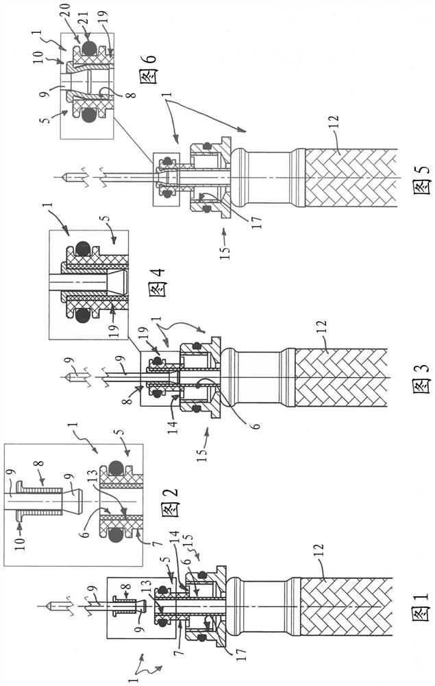
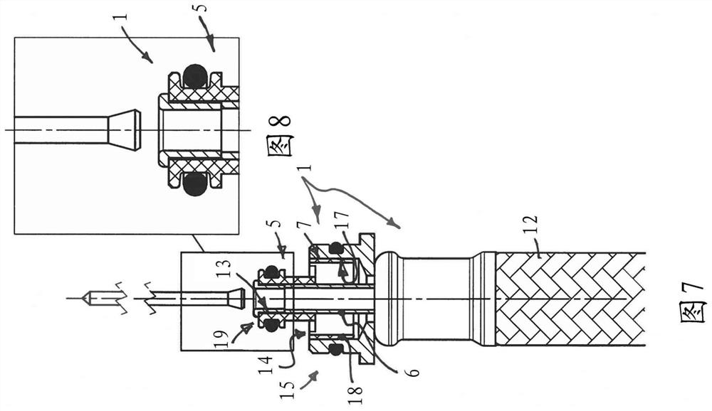
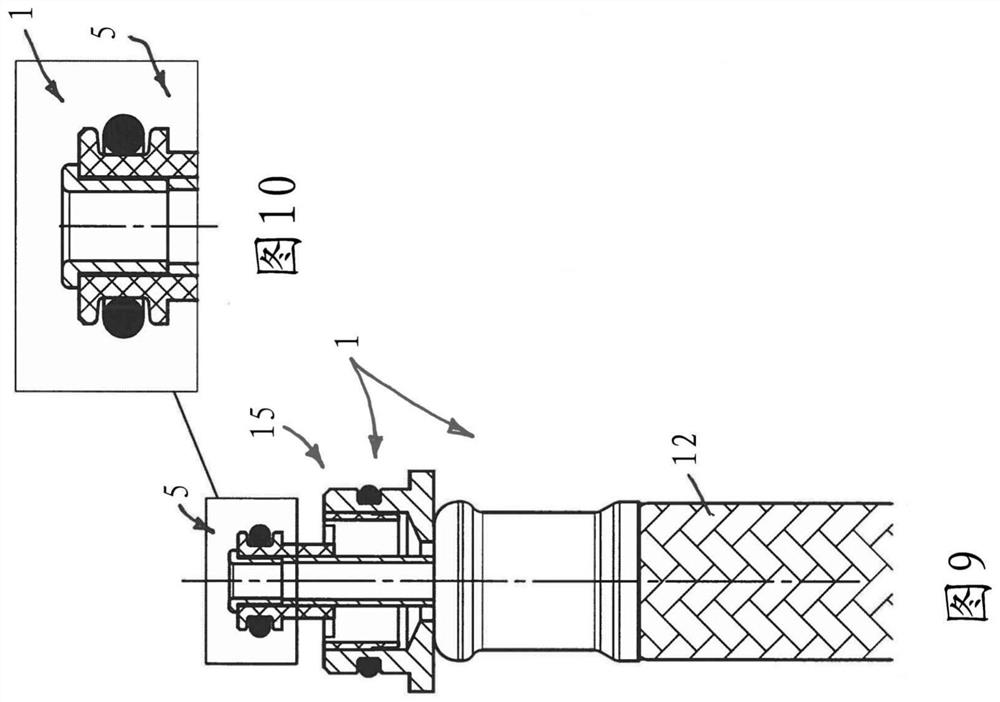
[0066] exist Figure 9 , 10 ; 12, 13; 20, 21 and 28, 29 show flexible hose lines in different embodiments 1, 2, 3 and 4, said hose line in its hose end region at least One has a hose connection 5 on it. exist Figures 1 to 8 , 14 to 19 and 22 to 27 show production steps according to various exemplary embodiments, which are provided for producing the hose lines 1 , 3 and 4 and for installing the at least one hose connection 5 .

[0067] The hose lines 1 , 2 , 3 and 4 have at least one flexible hose 6 with a hose connection 5 on at least one of its two hose end regions. By means of the hose connection 5 , the fluid guide can adjoin a further line section on the inflow side or the outflow side and continue the fluid guide.

[0068] For this purpose, the hose connection 5 has an outer part 7 which surrounds the hose end region of the at least one hose 6 and an inner part 8 which can be introduced into the inner hose cross-section of the hose 6 . In this case, the inner part 8...


PUM


Abstract

The invention relates to a hose joint (5), which can be fixed on a hose end area of at least one flexible hose (6) and is provided with an external part (7) surrounding the hose end area of the at least one hose and an internal part (8) capable of being introduced into the inner cross section of the hose. The hose joint is characterized in that the internal part is formed into a hollow rivet and can deform between an initial shape in the inner cross section of the hose capable of being introduced into the end part area of the hose and an expanded shape for tightly and fixedly clamping the at least one hose between the internal part and the external part. The invention further relates to a hose pipeline. The hose pipeline can also be formed into a two-cavity or multi-cavity hose pipeline. The invention also relates to a method for producing a hose joint on a hose end area of a flexible hose. They are associated with reduced manufacturing effort compared to the prior art.

Description

technical field [0001] The invention relates to a hose connection which can be fastened to a hose end region of at least one flexible hose and which has a hose end surrounding the at least one hose for this purpose. outer parts in the upper area and inner parts that can be introduced into the inner cross-section of the hose. [0002] The invention also relates to a hose line which has a hose connection of the above-mentioned type on at least one line end. The invention also relates to a hose line which is designed as a two-chamber or multi-chamber hose line and has an outer hose whose inner hose cross-section extends through at least An inner hose, wherein at least one hose coupling with a hose sleeve is assigned to the outer hose, the associated hose end region of the outer hose tightly surrounding the hose casing. [0003] The invention also relates to a method for producing a hose connection, in particular a hose connection of the above-mentioned type, in the region of t...

Claims


Application Information

Patent Timeline
IPC IPC(8): F16L33/20F16L11/04
CPCF16L33/30F16L11/10F16L33/213F16L11/22F16L33/01F16L11/16
Inventor H·赖因哈特
Owner NEOPERL
Learn More