Multidirectional movement type discharging mechanism

An unloading mechanism and motion-type technology, applied in mixers, transportation and packaging, mixer accessories, etc., can solve the problems of inability to fully open the unloading door panel, high safety hazards, and low unloading efficiency, and achieve compact structure and improved efficiency. The effect of unloading, the effect of simple structure

Active Publication Date: 2020-11-20
WUXI YUANFANG MACHINERY
View PDF3 Cites 0 Cited by
  • Summary
  • Abstract
  • Description
  • Claims
  • Application Information

AI Technical Summary

Problems solved by technology

[0005] Aiming at the deficiencies of the prior art, the present invention provides a multi-directional movement unloading mechanism, which overcomes the deficiencies of the prior art, has a reasonable design and a compact structure, and solves the problem that most of the existing mixers are manually unloaded. The unloading efficiency is low, and at the same time, there are high potential safety hazards. Even if some mechanical structures are used for unloading, the unloading door panel cannot be fully opened, resulting in the problem of low unloading efficiency. The invention can realize the unloading door panel through a simple structural combination. Move up and down to unload the mixer, and at the same time drive the unloading door to rotate, so that the mixer can be fully opened to improve the effect of unloading, which has strong practicability

Method used


Image

  • Multidirectional movement type discharging mechanism
  • Multidirectional movement type discharging mechanism
  • Multidirectional movement type discharging mechanism

Examples


Embodiment Construction

[0029] In order to make the purpose, technical solutions and advantages of the embodiments of the present invention clearer, the technical solutions in the embodiments of the present invention will be clearly and completely described below in conjunction with the drawings in the embodiments of the present invention. Obviously, the described embodiments It is a part of embodiments of the present invention, but not all embodiments. Based on the embodiments of the present invention, all other embodiments obtained by persons of ordinary skill in the art without creative efforts fall within the protection scope of the present invention.

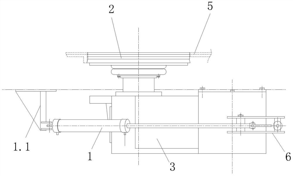
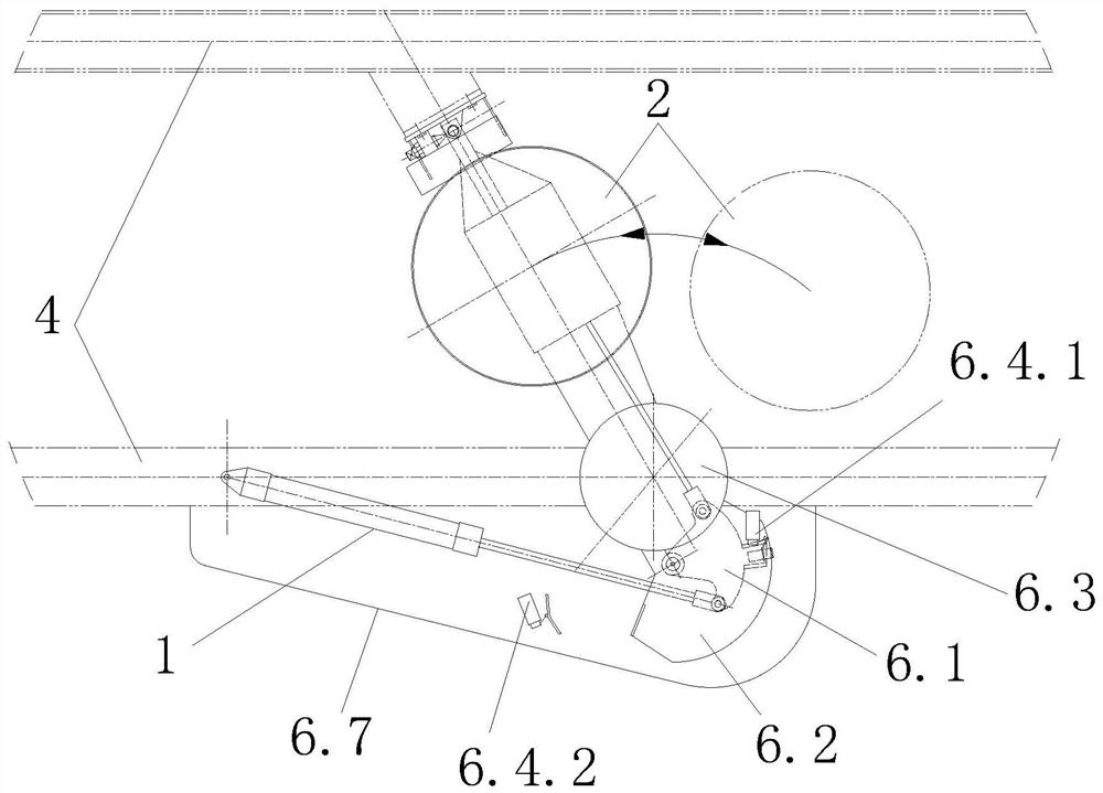
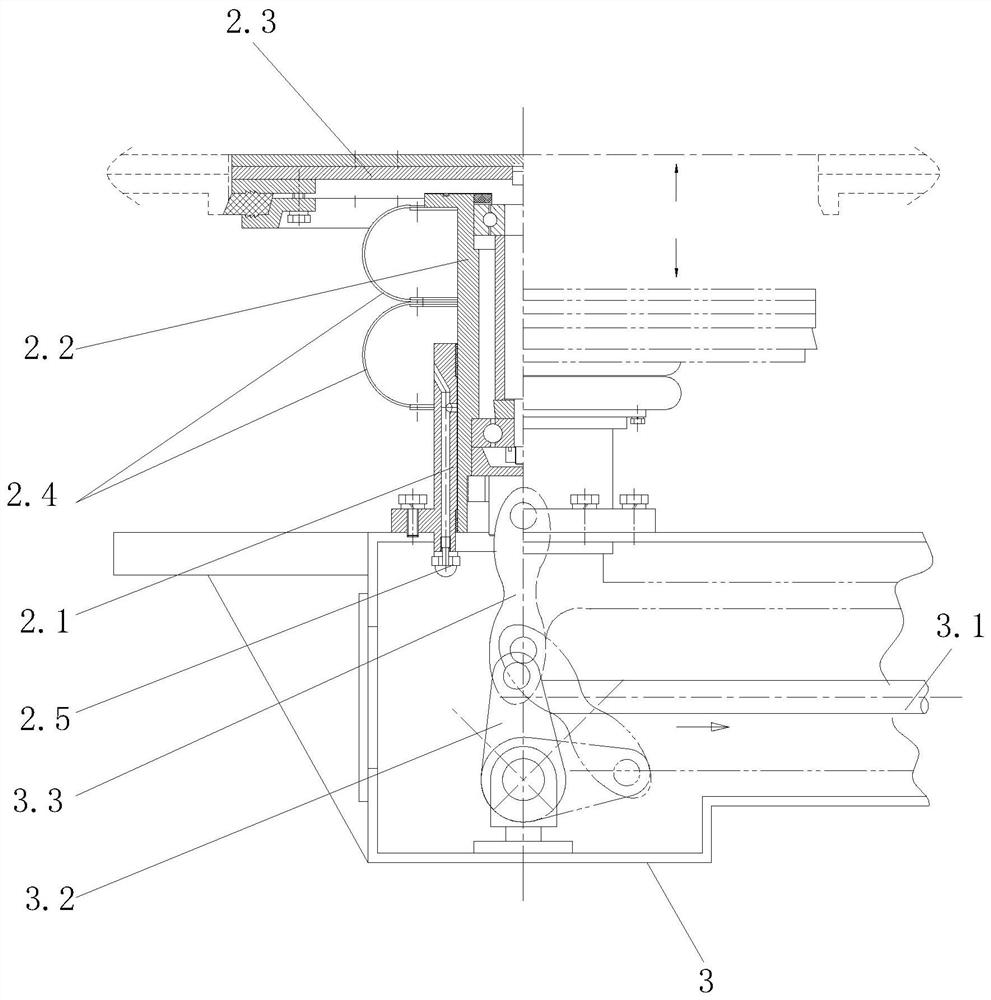
[0030] Refer to attached Figure 1-5 , a multi-directional movement type unloading mechanism, comprising a bucket 5, a discharge plate rotary lifting device 2 arranged at the lower end of the material bucket 5, the lower end of the discharge plate rotary lifting device 2 is provided with a rotary fixed frame 3, and the rotary One end of the fixed...


PUM


Abstract

The invention relates to the technical field of multidirectional movement discharging equipment, and provides a multidirectional movement type discharging mechanism which comprises a material cylinder, and a discharging plate rotary lifting device which is arranged at the lower end of the material cylinder , a rotary fixing frame is arranged at the lower end of the discharging plate rotary lifting device, one end of the rotary fixing frame is hinged to a disc, and the disc is rotationally connected to a mounting frame. The defects in the prior art are overcome; reasonable design is adopted, the structure is compact, the problems that most existing mixing machines adopt manual discharging, discharging efficiency is low, meanwhile, the potential safety hazard is high, even if a part of discharging is carried out by adopting a mechanical structure, a discharging door plate can not be opened completely, and discharging efficiency is low are solved; by means of simple structural combination, the discharging door plate can move up and down to discharge the mixing machine, and meanwhile, the discharging door plate can be driven to rotate, so that a mixing machine can be fully opened, thedischarging effect is improved, and very high practicability is achieved.

Description

technical field [0001] The invention relates to the technical field of multi-directional motion unloading equipment, in particular to a multi-directional motion unloading mechanism. Background technique [0002] The high-efficiency self-transformation mixer is one of the common equipment in the glass processing industry. In the actual use process, these mixers are all manually fed, and the efficiency of manual feeding is low. At the same time, due to the high temperature of the material, manual feeding is prone to safety hazards. Hidden danger. [0003] However, the traditional mechanical unloading device has a complex structure, and the unloading door cannot be fully opened, resulting in low unloading efficiency and affecting the unloading effect. Therefore, we propose a multi-directional motion unloading mechanism. Contents of the invention [0004] (1) Solved technical problems [0005] Aiming at the deficiencies of the prior art, the present invention provides a mult...

Claims


Application Information

Patent Timeline
Patent Type & Authority Applications(China)
IPC IPC(8): B01F15/02C03B1/00
CPCC03B1/00B01F35/75455B01F35/754
Inventor 邵彪陈晓红
Owner WUXI YUANFANG MACHINERY
Why Eureka
Try Eureka