Wiring device

A wiring device and lead wire technology, applied in the direction of connection, conductive connection, wire-wound connector, etc., can solve the problems of inconvenience, long time for rotating tightening or loosening, low assembly and disassembly efficiency, etc., and achieve the effect of easy exit.

Pending Publication Date: 2020-11-17
GUANGZHOU PANYU CABLE WORKS
View PDF0 Cites 0 Cited by
  • Summary
  • Abstract
  • Description
  • Claims
  • Application Information

AI Technical Summary

Problems solved by technology

The spring compression type greatly shortens the operation time, but due to the aging and damage of the spring, there will be problems that the contact surface is not fastened and reliable
Therefore, at present, many wiring devices adopt the screw compression type, but this method uses the operator to rotate the insulating rod, so that the wire clamp part of the wiring device moves upward with the bolt to clamp the wire, because the line distance of the clamp opening is nearly 6- 8CM, whether it is the operation process of tightening the wire clamp to clamp the wire or the operation process of unscrewing the wire clamp to exit the wire, the time of rotating tightening or loosening is too long, and more than half of the row distance is invalid stroke, which leads to the use of screw The labor intensity of the maintenance operators of the compression type wiring device is strong, it is very inconvenient, the assembly and disassembly efficiency is low, and time-consuming and laborious

Method used


Image

  • Wiring device
  • Wiring device

Examples


Embodiment Construction

[0024] In order to make the object, technical solution and advantages of the present invention clearer, the present invention will be further described in detail below in conjunction with the accompanying drawings and embodiments. It should be understood that the specific embodiments described here are only used to explain the present invention, not to limit the present invention.

[0025] It should be noted that when an element is said to be "fixed" to another element, it may be directly fixed to the other element, or there may be an intervening element, and when an element is said to be "connected" to another element, it Can be directly connected to another component, or indirectly through an intervening component. In addition, the terms "upper", "lower", "top", "bottom" and similar expressions used herein are for the purpose of illustration only, and do not represent the only embodiment.

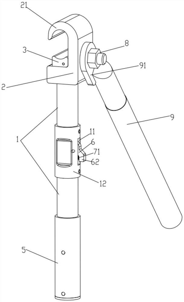
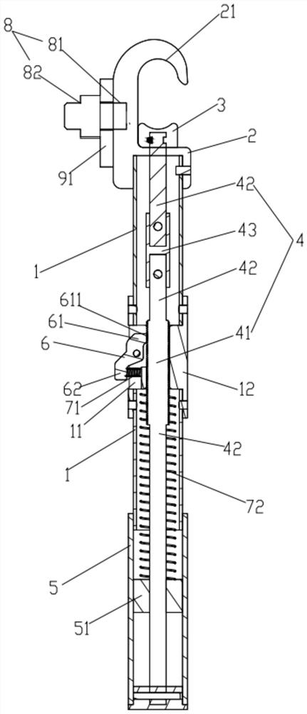
[0026] Such as Figure 1-2As shown, the wiring device includes a connecting sleeve ...


PUM


Abstract

The invention relates to the field of power equipment maintenance tools, in particular to a wiring device which comprises a connecting sleeve, a static chuck is fixedly connected to the upper end of the connecting sleeve, a movable chuck is correspondingly arranged below the static chuck, the movable chuck and the static chuck can be matched to clamp a wire, and the movable chuck is connected withthe top end of a sliding rod arranged in the connecting sleeve. The sliding rod can rotate in the connecting sleeve and can slide up and down in a reciprocating mode, a threaded section is arranged on the sliding rod, a locking key is hinged to the side wall of the connecting sleeve, the upper end of the locking key is a locking end, the lower end of the locking key is an unlocking end, and locking threads matched with threads of the threaded section are arranged on the side, facing the threaded section, of the locking end. The unlocking end is elastically connected with the accommodating groove through a locking key spring, and the locking end of the locking key is meshed with the thread of the threaded section in a natural state through the elastic force of the locking key spring. The wiring device is convenient and fast to operate, leads are firmly and reliably connected, and the operation time for connecting or loosening the leads can be greatly shortened.

Description

technical field [0001] The invention relates to the field of power equipment maintenance tools, in particular to a wiring device. Background technique [0002] In recent years, people have higher and higher requirements for the reliability of power supply. Power companies are using various methods to shorten construction and emergency repair time to ensure continuous power supply to customers. Wiring devices are often used in power system construction for emergency repair of cables to be repaired. For power supply or grounding, there are mainly two types of wiring devices commonly used at present: screw compression type and spring compression type, each of which has its own advantages and disadvantages. The screw-type contact surface is fastened and reliable, but the operation time is long. The spring compression type greatly shortens the operation time, but due to the aging and damage of the spring, there will be problems that the contact surface is not fastened and reliab...

Claims


Application Information

Patent Timeline
Patent Type & Authority Applications(China)
IPC IPC(8): H01R11/14H01R11/15H02G1/02
CPCH01R11/14H01R11/15H02G1/02
Inventor 黄应敏胡超强尤占山邹科敏邵源鹏高伟光冯家杰许翠珊冯泽华
Owner GUANGZHOU PANYU CABLE WORKS
Why Eureka
Try Eureka