
New energy anti-collision self-cleaning tide gauge

A self-cleaning, new energy technology, applied in the direction of cleaning methods and appliances, cleaning methods using tools, chemical instruments and methods, etc., can solve the problems of large investment, inconvenience, and the float cannot work normally, and achieve a high degree of integration. The effect of simple structure

Inactive Publication Date: 2020-11-17
南京玖昌智能科技有限公司
View PDF0 Cites 2 Cited by
  • Summary
  • Abstract
  • Description
  • Claims
  • Application Information

AI Technical Summary

Problems solved by technology

[0002] As we all know, tide observation is usually called water level observation, also known as tide inspection. The purpose of tide inspection is to understand the nature of local tides, and use the obtained tide observation data to calculate the tidal harmonic constant, mean sea level, depth datum, Tide forecasting and water level corrections at different times are provided for use by relevant military, transportation, fishery, surveying and mapping departments. The current tide gauge method mainly uses tide gauge stations, which require large investment and require personnel maintenance and observation, and are erected on the sea. The tide gauge needs to lay lines, which is extremely inconvenient, and there is a risk of being hit by floating objects such as ships. After a long time of use, a large number of marine organisms will adhere to the inside of the well, making the float unable to work normally. Therefore, it is necessary to design a new energy anti-collision automatic Clean the tide gauge to solve the above problems

Method used


Image

  • New energy anti-collision self-cleaning tide gauge
  • New energy anti-collision self-cleaning tide gauge
  • New energy anti-collision self-cleaning tide gauge

Examples


Embodiment Construction

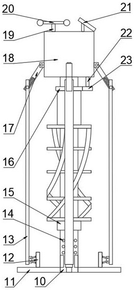
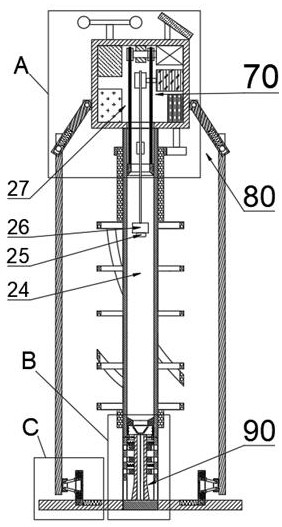
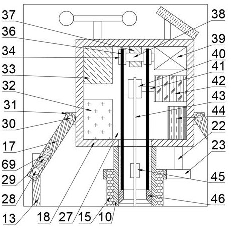
[0015] Combine below Figure 1-5 The present invention is described in detail, and for convenience of description, the orientations mentioned below are now stipulated as follows: figure 1 The up, down, left, right, front and back directions of the projection relationship itself are consistent.

[0016] combined with Figure 1-5 The new energy anti-collision self-cleaning tide gauge includes a tide gauge 10, the tide gauge 10 includes a water level chamber 24, a tide chamber 27, and a cleaning chamber 58, and the water level chamber 24 is equipped with The tide measuring mechanism 70, the self-cleaning mechanism 90 is provided in the cleaning chamber 58, the second hinge shaft 48 is fixed on the lower side of the left and right ends of the cleaning chamber 58, and the baffle plate 47 is hinged on the second hinge shaft 48 On the outer wall of the cleaning chamber 58 above the baffle plate 47, there are evenly distributed a number of water inlet and outlet holes 14 passing thr...


PUM


Abstract

The invention discloses a new energy anti-collision self-cleaning tide gauge which comprises a tide gauge well, the tide gauge well comprises a water level cavity, a tide gauge cavity and a cleaning cavity, a tide gauge mechanism is arranged in the water level cavity, a self-cleaning mechanism is arranged in the cleaning cavity, and second hinge shafts are fixedly arranged on the lower sides of the left end and the right end of the cleaning cavity. Thenew energy anti-collision self-cleaning tide gauge is simple in structure. At ordinary times, manual maintenance is not needed, natural resources can be fully utilized for power generation, no pipeline needs to be erected, tide can be detected only by erecting the device in a target sea area, detection data are transmitted back to a base station in a wireless mode, and the self-cleaning mechanism can prevent marine organisms and the like attached to the inner wall of the pipeline from affecting normal work of the floater. The anti-collision mechanism effectively protects the impeller structure and the device body which are relatively fragile, and the new energy anti-collision self-cleaning tide gauge can independently and efficientlycomplete tide inspection work on the offshore, and has a high integration degree.

Description

technical field [0001] The invention relates to the field of hydropower generation, in particular to a new energy anti-collision self-cleaning tide gauge. Background technique [0002] As we all know, tide observation is usually called water level observation, also known as tide inspection. The purpose of tide inspection is to understand the nature of local tides, and use the obtained tide observation data to calculate the tidal harmonic constant, mean sea level, depth datum, Tide forecasting and water level corrections at different times are provided for use by relevant military, transportation, fishery, surveying and mapping departments. The current tide gauge method mainly uses tide gauge stations, which require large investment and require personnel maintenance and observation, and are erected on the sea. The tide gauge needs to lay lines, which is extremely inconvenient, and there is a risk of being hit by floating objects such as ships. After a long time of use, a larg...

Claims


Application Information

Patent Timeline
IPC IPC(8): G01F23/40B08B1/00
CPCB08B1/00G01F23/40
Inventor 原金鸿
Owner 南京玖昌智能科技有限公司
Learn More