
Explosion-proof structure for smelting furnace

An explosion-proof structure and smelting furnace technology, applied in the field of smelting furnaces, can solve problems affecting the normal operation of the heating furnace

Inactive Publication Date: 2020-11-17
嵊州旧竹机械有限公司
View PDF5 Cites 0 Cited by
  • Summary
  • Abstract
  • Description
  • Claims
  • Application Information

AI Technical Summary

Problems solved by technology

[0002] The explosion-proof device of the smelting furnace is usually an opening on the pipe, and an explosion-proof cover is installed at the opening. When the pressure in the furnace is too high, the explosion-proof cover is opened to protect it. After the pressure in the furnace is normal, the manual operation makes the explosion-proof cover close. However, this kind of explosion-proof device cannot automatically reset and close after the explosion-proof cover is opened, and must be completed manually. functioning, there is a need for improvement

Method used


Image

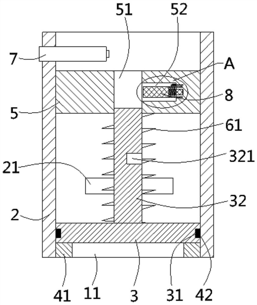
  • Explosion-proof structure for smelting furnace
  • Explosion-proof structure for smelting furnace
  • Explosion-proof structure for smelting furnace

Examples


Embodiment Construction

[0019] The specific implementation manners of the present invention will be further described in detail below in conjunction with the accompanying drawings and embodiments. The following examples are used to illustrate the present invention, but are not intended to limit the scope of the present invention.

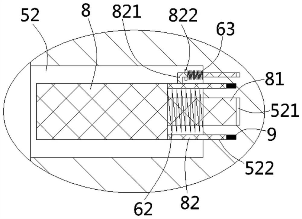
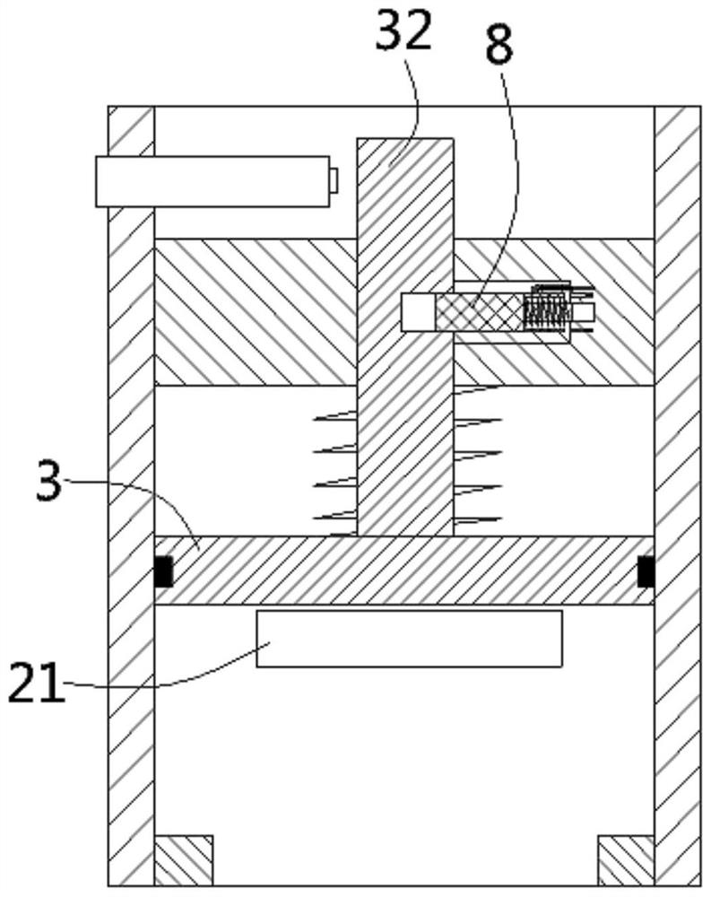
[0020] The following content reference Figure 1 to Figure 3 .

[0021] An explosion-proof structure for a smelting furnace according to the present invention includes a furnace body (not shown) of the smelting furnace, a pressure relief hole 11 is formed on the furnace body, and a pressure relief hole 11 is formed on the outer wall of the furnace body to match the pressure relief hole 11. The explosion-proof tube 2 connected by the pressure hole, the explosion-proof cover 3 is inserted in the explosion-proof tube, the lower end of the explosion-proof tube is inserted and fixed with a retaining ring 41, the lower end surface of the explosion-proof cover is pressed against...


PUM


Abstract

The invention discloses an explosion-proof structure for a smelting furnace. The structure comprises a furnace body. A pressure relief hole is formed in the furnace body; anti-explosion pipes are mounted on the outer wall of the furnace body; an anti-explosion cover is inserted into the anti-explosion pipes; a guide column is mounted on the anti-explosion cover; a positioning disc is inserted intothe anti-explosion pipes; a guide hole is formed in the center of the positioning disc; and the guide column is inserted into the guide hole. A first pressure spring is inserted into the guide columnin a sleeving mode; pressure relief grooves are formed in the side walls of the anti-explosion pipes; limiting holes are formed in the side wall of the guide column; a containing groove is formed inthe inner wall of the guide hole; a limiting rod is inserted into the containing groove; an inserting rod is mounted at one end of the limiting rod and sleeved by a second compressed spring in an inserted mode; the two ends of the second compressed spring abut against the limiting rod and the side wall of the containing groove respectively; and annular positioning plates are mounted on the limiting rod. Annular grooves are formed in the containing groove, the positioning plates are inserted into the annular grooves, electromagnets are fixed in the annular grooves, and the positioning plates are attracted to the electromagnets. According to the explosion-proof structure for the smelting furnace, the automatic closing of the anti-explosion cover can be realized after explosion-proof pressurerelief.

Description

Technical field: [0001] The invention relates to the technical field of smelting furnaces, in particular to an explosion-proof structure for smelting furnaces. Background technique: [0002] The explosion-proof device of the smelting furnace is usually an opening on the pipe, and an explosion-proof cover is installed at the opening. When the pressure in the furnace is too high, the explosion-proof cover is opened to protect it. After the pressure in the furnace is normal, the manual operation makes the explosion-proof cover close. However, this kind of explosion-proof device cannot automatically reset and close after the explosion-proof cover is opened, and must be completed manually. operation, it is necessary to improve it. [0003] In view of the above-mentioned defects, the designer actively researches and innovates, in order to create a new type of explosion-proof structure for smelting furnaces, so that it has more industrial value. Invention content: [0004] The ...

Claims


Application Information

Patent Timeline
IPC IPC(8): F16K17/04F16K17/164F27D21/00
CPCF16K17/042F16K17/0413F16K17/164F27D21/00F27D2021/0071
Inventor 谭化琴
Owner 嵊州旧竹机械有限公司
Learn More