Locking mechanism, automobile chassis and new energy vehicles
A technology of locking mechanism and locking head, which is applied in the direction of electric vehicles, vehicle energy storage, vehicle components, etc., can solve the problems of multiple movements of the battery box, poor versatility, and high complexity of the battery replacement mechanism
- Summary
- Abstract
- Description
- Claims
- Application Information
AI Technical Summary
Problems solved by technology
Method used
Image
Examples
Embodiment 1
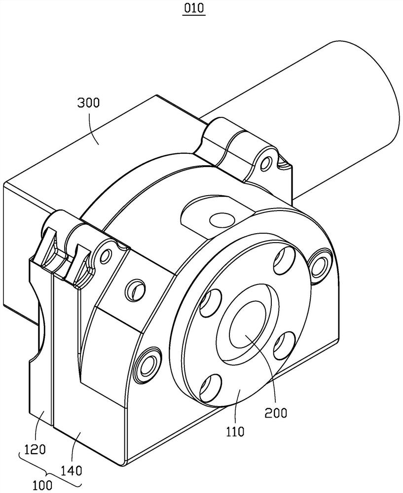
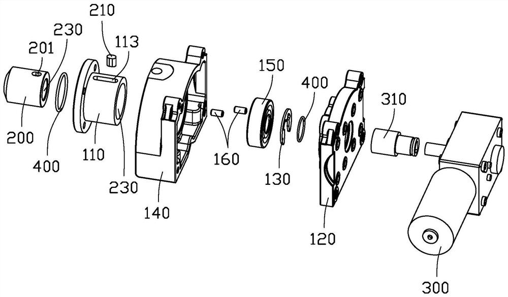
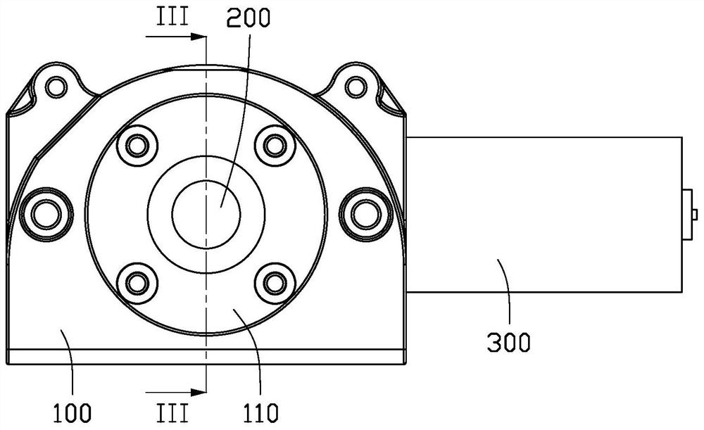
[0063] see figure 1 with figure 2 , an embodiment of the present application provides a locking mechanism 010, which is used to lock the battery box installed on a new energy vehicle. The locking mechanism 010 includes a fixed frame 100, a locking head 200 and a driving member 300, wherein the driving Part 300 includes a motor. The locking head 200 is connected with the fixed frame 100; the locking head 200 includes a first end and a second end oppositely arranged, the first end is provided with a feed thread, the second end is used to insert into the connecting hole of the battery box, and the driving member 300 Fixedly connected to the side opposite to the locking head 200 of the fixed frame 100, the output end of the driving member 300 is threadedly matched with the feed thread, so that when the output end of the driving member 300 rotates, the locking head 200 can advance axially. Give.
[0064] When the locking head 200 axially enters the connecting hole of the batter...
Embodiment 2
[0073] One embodiment of the present application provides an automobile chassis, including a chassis body, a battery box, and four locking mechanisms 010 as described in Embodiment 1; all locking mechanisms 010 are fixed on the chassis body, and the sides of the battery box A one-to-one corresponding connecting hole is provided with the locking mechanism 010; the locking head 200 in the locking mechanism 010 can extend into the connecting hole.
[0074] This automobile chassis includes a plurality of locking heads 200 of locking structure, and the locking heads 200 of multiple locking structures are inserted into corresponding connection holes to realize the fixing of the battery box. The actual operation process is as follows:
[0075] When the battery box is to be fixed, a locking command is sent to the driving parts 300 of all locking mechanisms 010, the output ends of the driving parts 300 rotate in the preset positive direction, the driving thread of the driving screw 310 ...
Embodiment 3
[0079] One embodiment of the present application provides a new energy vehicle (not shown in the figure), which uses electricity as power, and includes a vehicle frame and the vehicle chassis provided in Embodiment 2; the vehicle chassis is installed at the bottom of the vehicle frame.
[0080] The car chassis on this new energy vehicle includes a locking mechanism 010 of the battery box that can be quickly locked and unlocked. When the new energy vehicle is running, the locking mechanism 010 can effectively fix the battery box and prevent the vibration of the battery box from causing damage to the battery box. fixed invalidation.
PUM
 Abstract
Description
Claims
Application Information
 - R&D
- Intellectual Property
- Life Sciences
- Materials
- Tech Scout
- Unparalleled Data Quality
- Higher Quality Content
- 60% Fewer Hallucinations
Browse by: Latest US Patents, China's latest patents, Technical Efficacy Thesaurus, Application Domain, Technology Topic, Popular Technical Reports.
© 2025 PatSnap. All rights reserved.Legal|Privacy policy|Modern Slavery Act Transparency Statement|Sitemap|About US| Contact US: help@patsnap.com


