An Eccentric Clamping Mechanism for Lathe Tool

A clamping mechanism, lathe tool technology, applied in clamping, manufacturing tools, metal processing mechanical parts, etc., can solve the problems of increasing working time, cumbersome operation steps, shortening working time, etc., to shorten the time, simplify the operation steps, The effect of improving stability and adaptability

Active Publication Date: 2022-01-14
SUZHOU XINHE MACHINERY
View PDF12 Cites 0 Cited by
  • Summary
  • Abstract
  • Description
  • Claims
  • Application Information

AI Technical Summary

Problems solved by technology

[0005] The invention provides an eccentric clamping mechanism for lathe tools, which has a wide application range for the diameter of the drill bit, can realize manual disassembly and replacement of the drill bit, does not need to use other tools, and has simple operation steps and greatly shortened for the workpiece. The advantage of long working hours for hole position processing solves the problem that although the existing two drill bit clamping methods can effectively fix the drill bit, they each have a certain scope of application, resulting in the need to drill holes with large differences. According to the size of the hole, the drill fixture is replaced in time, so that in the process of drilling, not only the drill bit needs to be replaced in a timely manner, but also the appropriate fixture should be selected according to the diameter of the drill bit, which greatly increases the working time of the entire machine tool drilling operation. , and these two clamping and fixing methods require the use of tools to disassemble and replace the drill bit when replacing the drill bit, which makes the entire operation steps more cumbersome and time-consuming, which further increases the problem of the length of time it takes to process different apertures of the workpiece

Method used


Image

  • An Eccentric Clamping Mechanism for Lathe Tool
  • An Eccentric Clamping Mechanism for Lathe Tool
  • An Eccentric Clamping Mechanism for Lathe Tool

Examples


Embodiment Construction

[0022] The following will clearly and completely describe the technical solutions in the embodiments of the present invention with reference to the accompanying drawings in the embodiments of the present invention. Obviously, the described embodiments are only some, not all, embodiments of the present invention. Based on the embodiments of the present invention, all other embodiments obtained by persons of ordinary skill in the art without making creative efforts belong to the protection scope of the present invention.

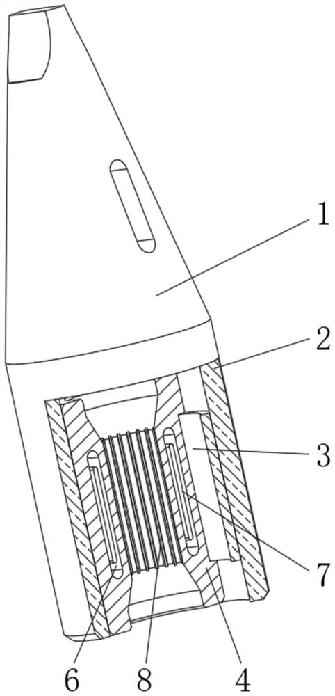
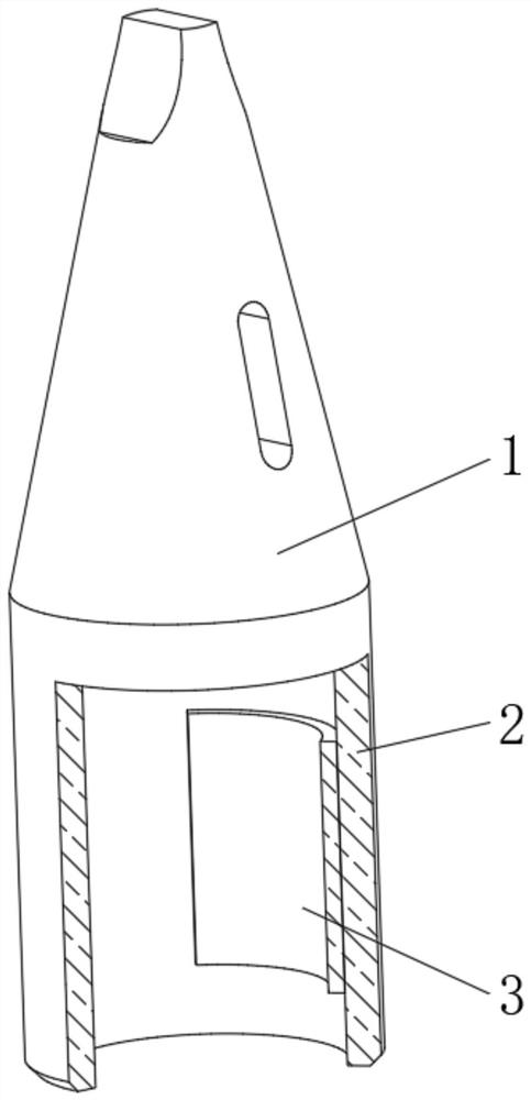
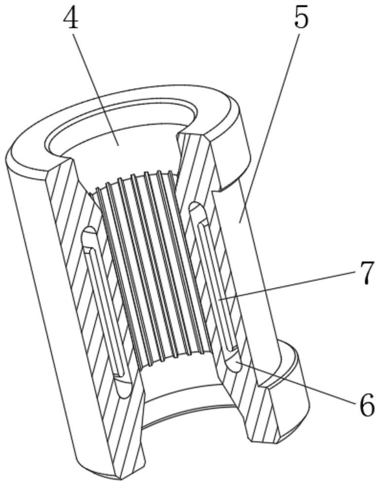
[0023] see Figure 1-4 , an eccentric clamping mechanism for lathe tools, including a mounting base 1, a transmission sleeve 2 is fixedly installed at the bottom of the installation base 1, and an eccentric slider is provided in the middle of one side of the inner cavity of the transmission sleeve 2 3. There is a movable sleeve 4 in the middle part of the inner cavity of the transmission sleeve 2, and the outer surface of the movable sleeve 4 is provided with ...


PUM


Abstract

The invention relates to the technical field of lathe processing equipment, and discloses an eccentric clamping mechanism for lathe tools, including a mounting bracket, a transmission sleeve is fixedly installed at the bottom end of the mounting bracket, and the transmission sleeve The middle part of one side of the inner cavity is provided with an eccentric slider, and the middle part of the transmission sleeve inner cavity is movable with a movable sleeve, and the outer surface of the movable sleeve is provided with an eccentric chute, and the eccentric chute and the transmission sleeve The eccentric sliders on the top are in contact with each other. The eccentric clamping mechanism for lathe tools is arranged symmetrically at an angle of ° between the two sides of the eccentric chute, so that no matter whether the transmission spindle rotates clockwise or counterclockwise, it can pass through the eccentric clamp on the transmission sleeve. The slider exerts a certain extrusion force on the movable sleeve, thereby avoiding the problem that the eccentric drill bit clamping mechanism can only clamp the drill bit along one direction, thereby effectively improving the stability and adaptability.

Description

technical field [0001] The invention relates to the technical field of lathe processing equipment, in particular to an eccentric clamping mechanism for lathe tools. Background technique [0002] In the machining industry, lathe machining is a very extensive hole processing device, mainly through the clamping mechanism to fix the connection between the drill bit and the transmission spindle, and then drive the drill bit to rotate to complete the drilling operation on the workpiece. [0003] However, the clamping methods of the existing drill clamps are mainly divided into two types. When facing a drill bit with a small diameter, the drill bit is fixed by thread extrusion, and when facing a drill bit with a large diameter, the clamping method is used to fix the drill bit. The method of layer-by-layer sleeve pressing is used to fix the drill bit. Although these two methods can effectively clamp and fix the drill bit, they have a certain scope of application respectively, so tha...

Claims


Application Information

Patent Timeline
Patent Type & Authority Patents(China)
IPC IPC(8): B23Q3/12
CPCB23Q3/12
Inventor 张超
Owner SUZHOU XINHE MACHINERY
Why Eureka
Try Eureka