
Delivery midwifery instrument for obstetrics and gynecology department

A midwifery instrument, obstetrics and gynecology technology, applied in obstetrics and gynecology instruments, sanitary equipment for toilets, dilators, etc. The effect of infection

Inactive Publication Date: 2020-11-17
何嘉鑫
View PDF1 Cites 1 Cited by
  • Summary
  • Abstract
  • Description
  • Claims
  • Application Information

AI Technical Summary

Problems solved by technology

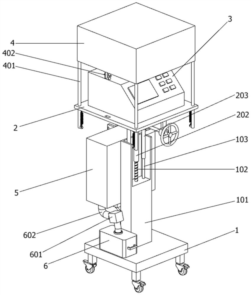
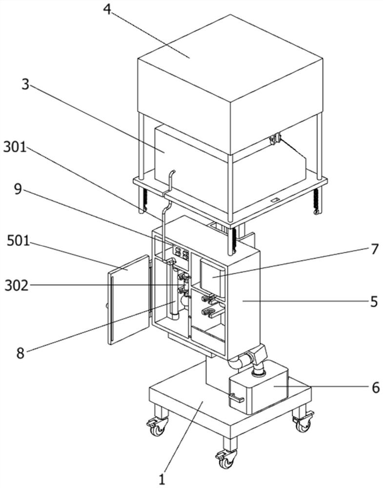
[0005] In order to solve the above-mentioned technical problems, the present invention provides obstetrics and gynecology obstetrics and obstetrics instruments to solve the following deficiencies in the actual use of the above-mentioned instruments for obstetrics, such as: 1. After the above-mentioned instruments for obstetrics are used, the The obstetric instrument lacks an effective cleaning structure, and at this time, the airbag and the airbag connection handle will be attached to a large number of attachments in the birth canal. Once these attachments drop onto the midwifery instrument and the ground, it will affect the environment of the delivery room ; 2. When the above-mentioned midwifery instrument is in use, the air bag and the air bag connection handle cannot be further disinfected, so that the air bag exposed to the air in the delivery room for a long time is easy to attach bacteria, which will cause infection to the puerpera's birth canal; 3 1. The above-mentioned midwifery instrument cannot be adjusted according to medical staff of different heights during use, thereby reducing the flexibility of the midwifery instrument during use

Method used


Image

  • Delivery midwifery instrument for obstetrics and gynecology department
  • Delivery midwifery instrument for obstetrics and gynecology department
  • Delivery midwifery instrument for obstetrics and gynecology department

Examples


Embodiment

[0035] as attached figure 1 to attach Figure 10 Shown:

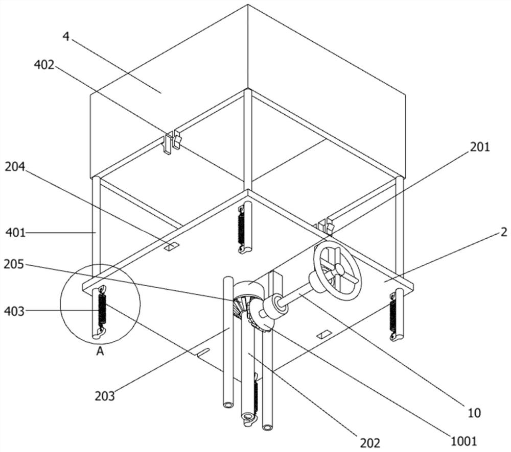
[0036] The present invention provides obstetrics and gynecology obstetrics and midwifery instrument, including: a base 1, the upper part of the base 1 is provided with a lifting mechanism 2, and the lifting mechanism 2 includes a threaded cylinder rotating sleeve 201, a threaded cylinder 202, a limit sliding cylinder 203, and a rectangular bayonet 204 With the first bevel gear 205, the central part of the bottom end surface of the lifting mechanism 2 is provided with a threaded cylinder rotating sleeve 201, and the bottom of the lifting mechanism 2 is connected with a threaded cylinder 202 through the threaded cylinder rotating sleeve 201, and the bottom end surface of the threaded cylinder rotating sleeve 201 is provided with a T Type card slot, the upper end of the threaded cylinder 202 is provided with a T-shaped block connected to the rotation of the T-shaped card slot, and the upper end of the outer peripheral sur...


PUM


Abstract

The invention provides a delivery midwifery instrument for the obstetrics and gynecology department, belongs to the technical field of delivery midwifery instruments. The problems that after the delivery midwifery instrument is used, because the delivery midwifery instrument lacks an effective cleaning structure, a large number of attachments in a birth canal are attached to an air bag and an airbag connecting handle, and once the attachments drop onto the delivery midwifery instrument and the ground, influences are brought to environment of a delivery room are solved. The delivery midwiferyinstrument comprises a base, and a lifting mechanism is arranged on the upper portion of the base. Through cooperation of a cleaning mechanism and a sewage collecting mechanism, during cleaning, a valve is opened, cleaning liquid in the cleaning mechanism is evenly sprayed to the air bag and the air bag connecting handle through a spray head, sewage obtained after cleaning enters the sewage collecting mechanism through a drainage hose, and an anti-backflow flap valve is installed at the water outlet end of the drainage hose, so that the phenomenon that peculiar smells and bacteria in the sewage collecting mechanism float to the air in the delivery room through the drainage hose is effectively avoided, and then the environment of the delivery room is prevented from being affected.

Description

technical field [0001] The invention belongs to the technical field of obstetric and obstetric delivery instruments, and more specifically relates to obstetric and gynecological delivery assistance instruments. Background technique [0002] The air bag midwifery instrument is a new product developed by Chinese scientific and technological personnel in the early 1990s. It uses the principle of bionics to replace the fetal head with an air bag. The birth canal can be used not only to induce labor but also to induce labor, which obviously shortens the labor process and reduces the pain of the mother. [0003] For example, the application number: CN201810512310.X The present invention discloses a digitally controlled superconducting visual bionic obstetrical instrument, including a base, a column is fixed in the middle of the upper part of the base, and a box is fixed at the upper end of the column, and the box An air pump is fixed inside the box body, and a display screen is f...

Claims


Application Information

Patent Timeline
IPC IPC(8): A61B17/42A61M29/04A61L2/10A61L2/26
CPCA61B17/42A61B2017/4225A61L2/10A61L2/26A61L2202/24A61M29/02
Inventor 何嘉鑫
Owner 何嘉鑫
Learn More