Method for calibrating height measurement center and camera center

A camera and laser altimeter technology, applied in the field of laser measurement, can solve problems such as difficulty in automation

Inactive Publication Date: 2020-11-13
QUICK INTELLIGENT EQUIP CO LTD
View PDF5 Cites 2 Cited by
  • Summary
  • Abstract
  • Description
  • Claims
  • Application Information

AI Technical Summary

Problems solved by technology

However, most of the existing laser position calibration mechanisms require manual operation, which is difficult to achieve automation

Method used


Image

  • Method for calibrating height measurement center and camera center

Examples


Embodiment Construction

[0015] The present invention is described in further detail now in conjunction with accompanying drawing. These drawings are all simplified schematic diagrams, which only illustrate the basic structure of the present invention in a schematic manner, so they only show the configurations related to the present invention.

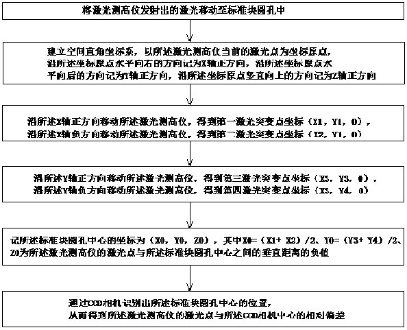
[0016] Such as figure 1 As shown, a method for calibrating the height measurement center and the camera center provided by the present invention includes the following steps:

[0017] S1. Move the laser emitted by the laser altimeter to the round hole of the standard block;

[0018] S2. Establish a space Cartesian coordinate system, take the current laser point of the laser altimeter as the origin of the coordinates, mark the direction horizontally to the right along the origin of the coordinates as the positive direction of the X-axis, and the direction horizontally backward along the origin of the coordinates It is recorded as the positive direction of the...


PUM


Abstract

The invention relates to a method for calibrating a height measurement center and a camera center. The method comprises steps of moving a laser altimeter in four directions, an X-axis positive direction, an X-axis negative direction, a Y-axis positive direction and a Y-axis negative direction, enabling the laser altimeter to sense the abrupt change of a laser reading, and obtaining the coordinatesof four abrupt change points; the midpoints of the two abrupt change points on the X axis in the X-axis direction and the midpoints of the two abrupt change points on the Y axis in the Y-axis direction representing the positions where laser height measurement is aligned with the center of the circular hole; and the specific position of the circular hole being identified through the camera so thatthe relative deviation between laser height measurement and the center of the camera is obtained, and the precision is very high. According to the method for calibrating the height measurement centerand the camera center provided by the invention, the CCD camera and the visual algorithm are used for positioning the circular hole of the standard block, and meanwhile, laser height measurement is controlled to carry out edge searching processing on the circular hole, so the relative positions of the CCD and the height measurement are confirmed.

Description

technical field [0001] The invention relates to the technical field of laser measurement, in particular to a method for calibrating a height measurement center and a camera center. Background technique [0002] Laser measurement is a non-contact measurement, which is widely used because of its advantages of not affecting the surface of the product being tested, high precision, large measurement range, and short detection time. Before using the laser to test the product, the position of the laser needs to be calibrated to ensure the accuracy of the laser test results. However, most of the existing laser position calibration mechanisms require manual operation, and it is difficult to realize automation. Contents of the invention [0003] The technical problem to be solved by the present invention is: in order to solve the above problems, the present invention provides a method for calibrating the height measurement center and the camera center, which realizes the laser auto...

Claims


Application Information

Patent Timeline
Patent Type & Authority Applications(China)
IPC IPC(8): G01C25/00
CPCG01C25/00
Inventor 刘泸姜加伟石文涛
Owner QUICK INTELLIGENT EQUIP CO LTD
Why Eureka
Try Eureka