high pressure water pump

A high-pressure water pump and housing technology, applied in the direction of pumps, pump components, pump devices, etc., can solve problems such as piston wear, piston damage, and unstable spray pressure, so as to avoid accumulation, improve service life, and avoid alternate changes. Effect

Active Publication Date: 2022-02-01
浙江飞驰机电有限公司
View PDF7 Cites 0 Cited by
  • Summary
  • Abstract
  • Description
  • Claims
  • Application Information

AI Technical Summary

Problems solved by technology

[0005] The plunger-type high-pressure water pump in the prior art adopts a synchronous plunger-type system, and realizes the synchronous change of the inner space of the corresponding guide cylinder through a single or multiple synchronously moving pistons, but the movement of a single piston or the synchronous movement of multiple pistons, The high-pressure pump internally sucks liquid and sprays liquid alternately. This reciprocating and alternating working principle has great disadvantages. When performing high-pressure liquid spraying, the pressure of the sprayed liquid will alternately change, that is, the spraying pressure is unstable. At the same time, because the plunger-type high-pressure water pump is equipped with a constantly moving piston, when the high-pressure water pump sucks in more impurities, these impurities will seriously affect the normal operation of the piston, accelerate the wear of the piston, and even cause damage to the piston.

Method used


Image

  • high pressure water pump
  • high pressure water pump
  • high pressure water pump

Examples


Embodiment approach

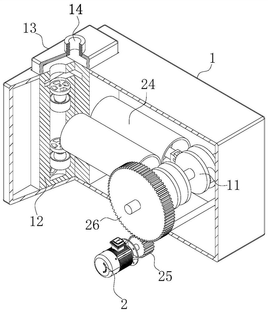
[0028] As an embodiment of the present invention, the front and rear side walls of the housing 1 are jointly rotatably connected with a rotating column directly below the crankshaft 11; the outer arc surface of the rotating column is close to the front wall of the housing 1 The first gear 25 is fixedly connected; the front end surface of the housing 1 is fixedly connected with the motor 2 at the position of the rotating column, and the output shaft of the motor 2 is fixedly connected with the rotating column; the outer arc surface of the crankshaft 11 is fixedly connected with Second gear 26, meshing connection between the second gear 26 and the first gear 25, and the diameter size of the second gear 26 is greater than the diameter size of the first gear 25; during work, by setting the first gear 25 and the second gear 26 , the motor 2 drives the first gear 25 to rotate, the first gear 25 drives the second gear 26 to rotate through the meshing mode, the rotation of the cranksha...


PUM


Abstract

The invention belongs to the technical field of water pumps, and specifically relates to a high-pressure water pump, which includes a housing, a motor and a ball valve; the front and rear side walls of the housing are jointly rotated and connected to the same crankshaft at the position close to the right side of the housing; The front end of the housing is fixedly connected with a motor; the inside of the housing is fixedly connected with a guide cylinder; the inside of the guide cylinder is slidably connected with a piston; the inner left side of the housing is fixedly connected at the position of the guide cylinder There is a plug box; the interior of the two plug boxes is fixedly connected with guide blocks in the upper and lower directions of the corresponding guide cylinders; ball valves are arranged above the guide blocks; through the present invention, the high-pressure water pump is effectively realized. Continuous and stable water spraying avoids the alternating change of spraying water pressure, and even when the motor rotates at a low speed, there will be no flow interruption. By filtering the imported water, a large amount of impurities in the water are prevented from being sucked into the high-pressure water pump. Internally, the service life of the high-pressure water pump is greatly improved.

Description

technical field [0001] The invention belongs to the technical field of water pumps, in particular to a high-pressure water pump. Background technique [0002] The most widely used high-pressure water pump is the miniature high-pressure water pump. Because of its high pressure, small size, easy to carry, and can be driven by a car battery, it is often used for cleaning, spraying, spraying, boosting, and pumping. [0003] The plunger-type high-pressure water pump is an important device of the hydraulic system. It relies on the reciprocating movement of the plunger in the cylinder to change the volume of the sealed working chamber to achieve liquid suction and oil pressure. The plunger pump has a high rated pressure, It has the advantages of compact structure, high efficiency and convenient flow adjustment. [0004] According to CN205805846U, a purely mechanical reciprocating high-pressure plunger water pump has made technological innovations on the basis of traditional hydrau...

Claims


Application Information

Patent Timeline
Patent Type & Authority Patents(China)
IPC IPC(8): F04B17/03F04B23/06F04B53/00F04B53/10
CPCF04B17/03F04B23/06F04B53/00F04B53/1002
Inventor 阮海建
Owner 浙江飞驰机电有限公司
Why Eureka
Try Eureka