
Diesel engine with heat dissipation system

A diesel engine and heat dissipation system technology, which is applied to the cooling of engine components, machines/engines, and engines, can solve problems such as high cost, poor heat dissipation effect, and engine cooling effect interference, and achieve the effect of improving heat dissipation

Pending Publication Date: 2020-11-13
湖北美标康盛动力科技有限公司
View PDF3 Cites 1 Cited by
  • Summary
  • Abstract
  • Description
  • Claims
  • Application Information

AI Technical Summary

Problems solved by technology

With the continuous development of science and technology, diesel engine technology has been comprehensively improved, higher and higher thermal efficiency, and stable improvement of power performance, and the radiator of diesel engine is an indispensable important part of diesel engine. The existing radiator , air-cooled intercooler, and oil cooler are independently arranged in different positions and have a large volume. When the fan is blowing, it may be blocked by the intercooler and affect the heat of the radiator and oil cooler. Exchange efficiency, and the unreasonable arrangement of the radiator may make the heat dissipation effect relatively poor, the cost is also relatively expensive, and it also greatly interferes with the cooling effect of the engine
[0005] The diesel engine will generate a lot of heat during the working process. Whether the heat is dissipated in time directly affects the working state of the engine. The traditional air cooling method has poor heat dissipation effect, and it is easy to accumulate dust on the surface of the engine, which affects the normal use of the engine.

Method used


Image

  • Diesel engine with heat dissipation system
  • Diesel engine with heat dissipation system
  • Diesel engine with heat dissipation system

Examples


Embodiment Construction

[0022] It should be noted that, in the case of no conflict, the embodiments in the patent of the present invention and the features in the embodiments can be combined with each other.

[0023] In the description of the patent of the present invention, it should be understood that the terms "center", "longitudinal", "transverse", "upper", "lower", "front", "rear", "left", "right", The orientations or positional relationships indicated by "vertical", "horizontal", "top", "bottom", "inner", "outer", etc. are based on the orientation or positional relationships shown in the drawings, and are only for the convenience of describing the present invention Patents and simplified descriptions do not indicate or imply that the device or element referred to must have a specific orientation, be constructed and operate in a specific orientation, and therefore should not be construed as limiting the patent of the invention. In addition, the terms "first", "second", etc. are used for descript...


PUM


Abstract

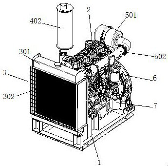
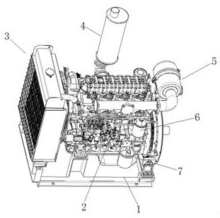
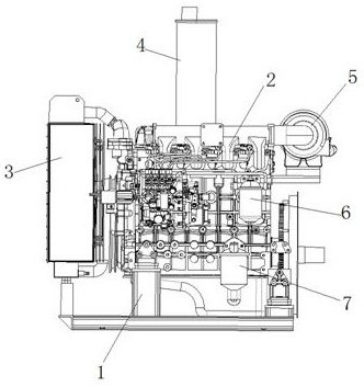
The invention discloses a diesel engine with a heat dissipation system. An engine body is installed on a supporting frame, a heat dissipation assembly is installed at one end of the engine body, bothof an exhaust assembly and an air inlet assembly communicate with the engine body, the heat dissipation assembly comprises a heat dissipation box cover, a heat dissipation fan and an evaporation refrigerator, the heat dissipation fan is arranged in the inner part of the heat dissipation box cover, the heat dissipation fan is fixed to the crankshaft output end of the engine body, and the evaporation refrigerator is installed at one end of the heat dissipation box cover. The diesel engine with the heat dissipation system has the beneficial effects that the diesel engine is provided with the heat dissipation assembly, the exhaust assembly and the air inlet assembly, the exhaust assembly and the air inlet assembly are each provided with a filter element, filtering are carried out on inlet airand outlet air, impurities are prevented from entering the engine, waste gas is prevented from being exhausted out of the external air, and heat dissipation is carried out on the engine through the heat dissipation assembly by using an air cooling mode, so that the service life of an engine shell is prevented from being influenced by long-term over-high temperature; and on the other hand, the heat dissipation effect can be further improved through the heat dissipation fan assembly, and meanwhile accumulated dust on the engine shell can be blown away.

Description

technical field [0001] The patent of the present invention relates to the technical field of diesel engines, in particular to a diesel engine with a cooling system. Background technique [0002] The development status of the automobile industry is one of the important symbols to measure the level of a country's industrialization. It occupies an important position in the construction of the national economy and national defense, and is closely related to the quality of life of the people. In the entire automobile industry, diesel engines are gradually becoming the main power of automobiles due to their advantages such as high thermal efficiency, good adaptability, and large output power; compared with other internal combustion engines, diesel engines have high power, high fuel thermal efficiency, long service life, and excellent starting performance Good, low carbon monoxide (CO) and hydrocarbon (HC) emissions, low fuel consumption and a series of advantages. [0003] Diesel...

Claims


Application Information

Patent Timeline
IPC IPC(8): F01P11/12F01P11/00
CPCF01P11/12F01P11/00
Inventor 张辉周红平
Owner 湖北美标康盛动力科技有限公司
Learn More