High-precision writing and drawing robot
A robot and high-precision technology, which is applied in writing utensils, manipulators, printing, etc., can solve problems that affect repeat positioning accuracy, affect drawing accuracy, and carriage shaking, so as to improve repeat positioning accuracy, improve drawing accuracy, and solve twisting problem effect
- Summary
- Abstract
- Description
- Claims
- Application Information
AI Technical Summary
Problems solved by technology
Method used
Image
Examples
Embodiment 1
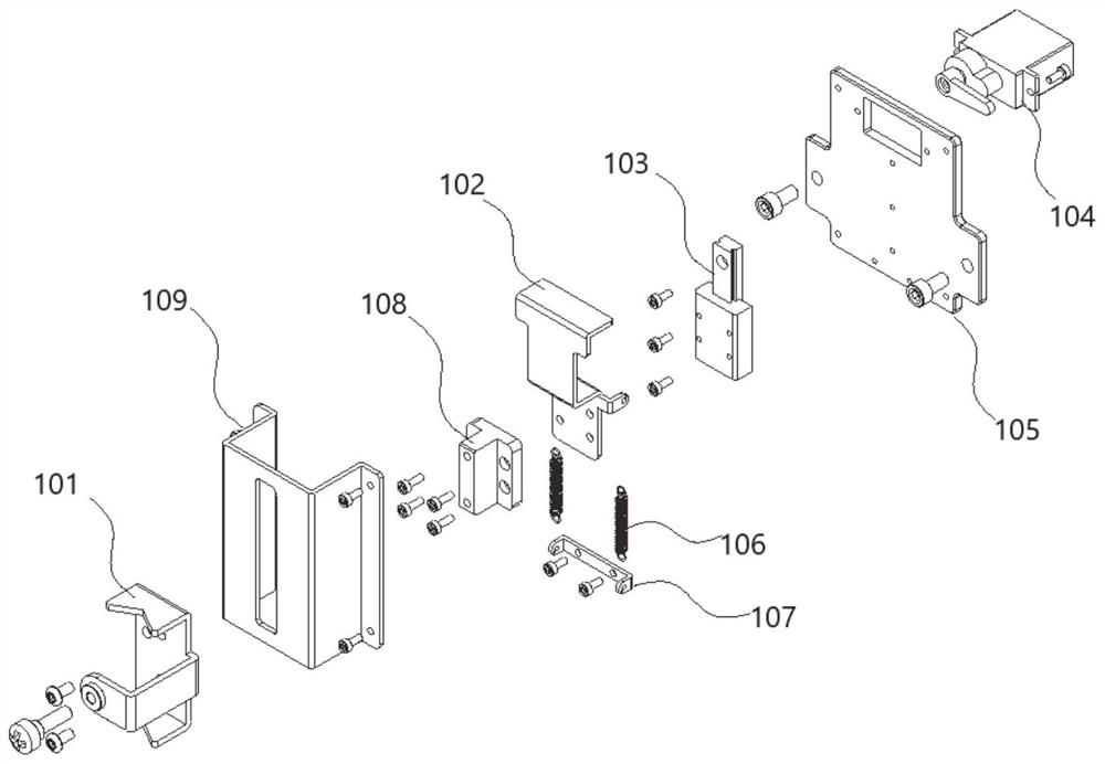
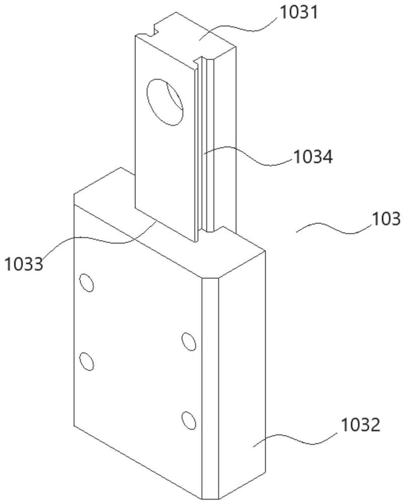
[0069] figure 1 It is an exploded view of the pen holder assembly in an embodiment of the present application, figure 2 It is a schematic diagram of a linear guide rail module in an embodiment of the present application, combined with the following figure 1 and figure 2 This embodiment will be specifically described.
[0070] A high-precision writing and drawing robot, comprising a pen holder assembly 100, the pen holder assembly 100 sequentially includes a pen holder 101, a support plate 102, a linear guide rail module 103, and a driving source 104 along a first direction; the linear guide rail module 103 includes a track rod 1031 and a slide Block 1032, the slider 1032 is slidably connected to the rail bar 1031 along the second direction; one end of the support plate 102 is fixedly connected to the slider 1032; the other end of the support plate 102 is fixedly connected to the pen holder 101; the driving source 104 is fixed to the support plate 102 connect.
[0071] ...
Embodiment 2
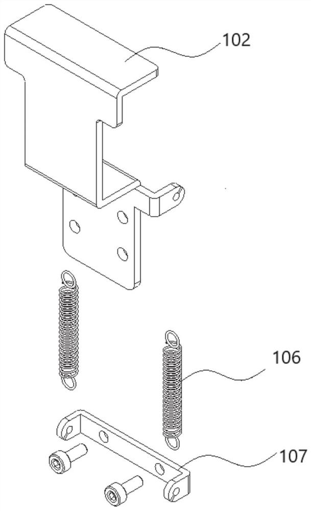
[0086] image 3 It is a schematic diagram of a spring, a support plate and a stopper in an embodiment of the present application, Figure 4 It is a schematic diagram of the partial assembly structure of the pen holder assembly in an embodiment of the present application, Figure 5 It is a structural schematic diagram of a pen holder in an embodiment of the present application, Figure 6 It is another schematic structural view of the pen holder in one embodiment of the present application, combined below Figure 1 to Figure 6 This embodiment will be specifically described.
[0087] On the basis of the above embodiments, further, the pen holder assembly 100 also includes a base plate 105, a spring 106 and a stopper 107; the base plate 105 is installed between the linear guide module 103 and the driving source 104, and the driving source 104 passes through the base plate 105 is fixedly connected with the support plate 102; the track bar 1031 in the linear guide module 103 is f...
Embodiment 3
[0101] Figure 7 It is a schematic structural diagram of a cross-shaped easel in an embodiment of the present application, Figure 8 It is a structural schematic diagram of a fastening belt device on the fourth end seat in an embodiment of the present application, Figure 9 It is a structural schematic diagram of another fastening belt device on the fourth end seat in an embodiment of the present application, Figure 10 for Figure 9 An exploded view of the fastening belt device in, Figure 11 It is a schematic diagram of a partial structure of a cross-shaped easel in an embodiment of the present application, combined below Figure 1 to Figure 11 This embodiment will be specifically described.
[0102] Such as Figure 7 As shown, the high-precision writing and drawing robot also includes a cross-shaped easel 200. The cross-shaped easel 200 includes a first polished rod 2011 and a second polished rod 2021 perpendicular to each other; the two ends of the first polished rod ...
PUM
 Abstract
Description
Claims
Application Information
 - R&D Engineer
- R&D Manager
- IP Professional
- Industry Leading Data Capabilities
- Powerful AI technology
- Patent DNA Extraction
Browse by: Latest US Patents, China's latest patents, Technical Efficacy Thesaurus, Application Domain, Technology Topic, Popular Technical Reports.
© 2024 PatSnap. All rights reserved.Legal|Privacy policy|Modern Slavery Act Transparency Statement|Sitemap|About US| Contact US: help@patsnap.com


