
Object detection method and system based on dynamic sample selection and loss consistency

An object detection and consistency technology, applied in the field of pattern recognition, can solve problems such as non-dynamicity, dynamic changes of positive and negative samples, and inconsistency

Active Publication Date: 2020-11-10
INST OF AUTOMATION CHINESE ACAD OF SCI
View PDF4 Cites 15 Cited by
  • Summary
  • Abstract
  • Description
  • Claims
  • Application Information

AI Technical Summary

Problems solved by technology

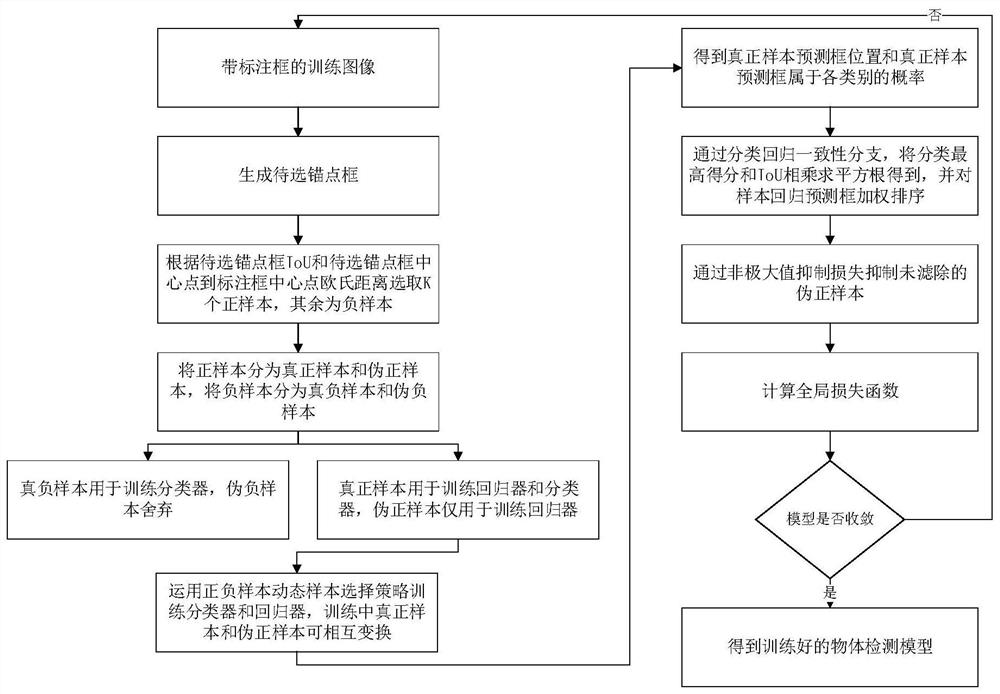
However, there are two problems in the current object detection algorithm. One is the non-dynamic problem of training. When the samples are divided into positive and negative samples at the beginning of training, this fixed division result is used in the whole training process, but as the training progresses The samples are changing, and the division of positive and negative samples does not change dynamically as the training progresses; the second is the problem of training inconsistency. There are two inconsistencies in the training phase of object detection. The first non-consistency Consistency means that the prediction frame with the highest score in the detection may not be the prediction frame with the most accurate position. The second inconsistency is reflected in the filtering of false detections. The non-maximum value suppression algorithm is used to filter false detections in the test phase, while training stage does not involve this operation
In general, the inconsistency of the classification and regression tasks and the inconsistency of non-maximum suppression in the training and testing phases can easily lead to the problem of not being able to get the best classification and object position.

Method used


Image

  • Object detection method and system based on dynamic sample selection and loss consistency
  • Object detection method and system based on dynamic sample selection and loss consistency
  • Object detection method and system based on dynamic sample selection and loss consistency

Examples


Embodiment Construction

[0062] The application will be further described in detail below in conjunction with the accompanying drawings and embodiments. It should be understood that the specific embodiments described here are only used to explain related inventions, not to limit the invention. It should also be noted that, for the convenience of description, only the parts related to the related invention are shown in the drawings.

[0063] It should be noted that, in the case of no conflict, the embodiments in the present application and the features in the embodiments can be combined with each other. The present application will be described in detail below with reference to the accompanying drawings and embodiments.

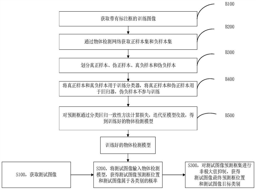
[0064] The present invention provides an object detection method based on dynamic sample selection and loss consistency. The method includes step S100-step S300;

[0065] Step S100, acquiring a test image;

[0066] Step S200, input the test image into the trained object detection m...


PUM


Abstract

The invention belongs to the field of pattern recognition, particularly relates to an object detection method and system based on dynamic sample selection and loss consistency, and aims to solve the problems of insufficient object recognition accuracy and performance. The method comprises the following steps: firstly, acquiring a test image, dynamically selecting a positive sample and a negative sample in a training process, introducing a non-maximum suppression loss, and acquiring a prediction frame position of the test image and a probability that a prediction frame belongs to each categoryby an object detection model; and acquiring the target category and the prediction box position of the optimal test image through non-maximum suppression. Each annotation box generates the same numberof positive samples, the optimizer can fairly treat each training sample, and the regression loss function is re-weighted by predicting a IOU of each prediction box through dynamic sample selection,so that the optimal detection result is more accurate, and the detection accuracy is improved. In the training stage, a non-maximum suppression loss function is introduced to punish false detection generated in training, so that the false detection is reduced in the test stage.

Description

technical field [0001] The invention belongs to the field of pattern recognition, and in particular relates to an object detection method and system based on dynamic sample selection and loss consistency. Background technique [0002] Object detection is a crucial technical field of computer vision, and it is a basic module in multiple high-level vision tasks. The current object detection methods are mainly divided into two mainstream methods based on anchor boxes and without anchor boxes. Both methods need to define positive and negative samples for classification and regression tasks in the training phase, and both need to use the non-maximum suppression algorithm to output the optimal results in the testing phase. However, there are two problems in the current object detection algorithm. One is the non-dynamic problem of training. When the samples are divided into positive and negative samples at the beginning of training, this fixed division result is used in the whole ...

Claims


Application Information

Patent Timeline
Patent Type & Authority Applications(China)
IPC IPC(8): G06K9/62G06N3/04
CPCG06N3/045G06F18/24G06F18/214
Inventor 雷震张士峰罗卓群张永明
Owner INST OF AUTOMATION CHINESE ACAD OF SCI
Learn More