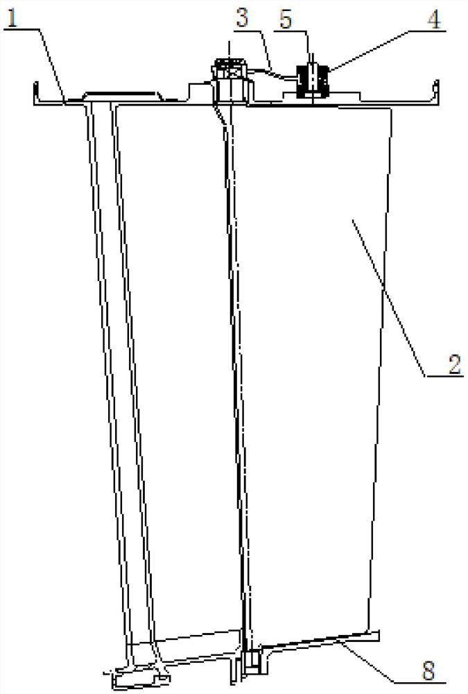
Stator blade angle adjusting mechanism and stator casing structure with same

A stator blade and angle adjustment technology, which is applied in the direction of machines/engines, mechanical equipment, liquid fuel engines, etc., can solve problems such as poor economy, complex structure, and inaccurate control of the rotation angle of stator blades

Active Publication Date: 2020-11-10
AECC SHENYANG ENGINE RES INST
View PDF6 Cites 10 Cited by
  • Summary
  • Abstract
  • Description
  • Claims
  • Application Information

AI Technical Summary

Problems solved by technology

[0004] 1) It is necessary to design corresponding locking plates, gaskets, joint bearings, split pins, collars and other parts for connection between its various parts. The structure is complex, the number of parts is large, the weight is heavy, the assembly process is cumbersome, the economy is poor, and some parts are easy Wear and tear affect the reliability of the linkage structure of the stator blades;
[0005] 2) It realizes synchronous adjustment of the rotation angle of each stator blade through the rotation of the linkage ring, which has high requirements on the stiffness of the components, and the control of the rotation angle of the stator blade is not accurate enough

Method used


Image

  • Stator blade angle adjusting mechanism and stator casing structure with same
  • Stator blade angle adjusting mechanism and stator casing structure with same
  • Stator blade angle adjusting mechanism and stator casing structure with same

Examples


Embodiment Construction

[0044] In order to make the technical solution of the present application and its advantages clearer, the technical solution of the present application will be further clearly and completely described in detail below in conjunction with the accompanying drawings. It can be understood that the specific embodiments described here are only part of the application Examples are only used to explain the present application, not to limit the present application. It should be noted that, for the convenience of description, only the parts related to the present application are shown in the drawings, and other relevant parts can refer to the general design. In the case of no conflict, the embodiments in the application and the technologies in the embodiments Features can be combined with each other to obtain new embodiments.

[0045] In addition, unless otherwise defined, the technical terms or scientific terms used in the description of the application shall have the usual meanings und...


PUM


Abstract

The invention belongs to the field of gas compressor stator blade angle adjustment design, and particularly relates to a stator casing structure. The stator casing structure is characterized by comprising a stator casing, a plurality of stator blades, a stator blade angle adjusting mechanism and a linkage ring; a plurality of mounting holes distributed in the circumferential direction are formed in the stator casing; the plurality of stator blades are distributed in the stator casing in the circumferential direction; the shaft diameter of each stator blade correspondingly extends out of one mounting hole; the stator blade angle adjusting mechanism comprises a plurality of rocker arms, and one end of each rocker arm is correspondingly connected with one shaft diameter; the linkage ring sleeves the periphery of the stator casing and is hinged to the other end of each rocker arm; each rocker arm can rotate relative to the linkage ring and can slide in the circumferential direction of thelinkage ring; and the linkage ring can move in the axial direction of the stator casing so as to drive all the rocker arms to move, and therefore the stator blades can rotate. In addition, the invention relates to the stator blade angle adjusting mechanism, and the stator blade angle adjusting mechanism has all characteristics of the stator blade angle adjusting mechanism in the stator casing structure.

Description

technical field [0001] The application belongs to the field of angle adjustment design of compressor stator vanes, and in particular relates to a stator vane angle adjustment mechanism and a stator casing structure thereof. Background technique [0002] In order for the compressor in the engine to work stably, it is necessary to adjust the flow of air flowing through the compressor according to the actual situation. For this purpose, the angle of each stator blade in the compressor can be adjusted, and the angle adjustment mechanism can be used to adjust the synchronous rotation of each stator blade to change each stator blade synchronously. The angle of the stator blades is used to adjust the air flow through the compressor. [0003] Each stator vane in the compressed air is arranged between the compressor stator casing and the inner ring, distributed along the circumference, and its shaft diameter corresponds to protruding from the installation hole on the compressor stato...

Claims


Application Information

Patent Timeline
IPC IPC(8): F04D29/46F04D29/42F04D29/56F04D29/52
CPCF04D29/462F04D29/4206F04D29/563F04D29/522
Inventor 韩乐男王坤于长旺
Owner AECC SHENYANG ENGINE RES INST
Why Eureka
Try Eureka